KEYLESS ACCESS WITH PUSH BUTTON START SYSTEM (DIAGNOSTICS) > Diagnostic Procedure with Diagnostic Trouble Code (DTC)
DTC DETECTING CONDITION:
There is a malfunction in the output circuit from the power supply CM to the accessory.
TROUBLE SYMPTOM:
Systems do not operate at the ACC position.
CAUTION:
When the power supply CM is replaced with a new unit, and the battery ground terminal is connected, it will become ignition ON. Also, if the battery is disconnected, it will resume to a condition with the battery cut off.
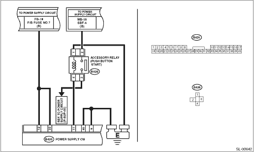
WIRING DIAGRAM:

1.CHECK FUSE.
1) Turn the ignition switch to OFF.
|
|
Replace the fuse (FB-18). If the replaced fuse blows out easily, repair the short circuit in the harness between the fuse and body integrated unit.
|
|
2.CONTINUITY CHECK OF WIRING HARNESS.
1) Disconnect connector (B420) from the power supply CM.
2) Measure the voltage between the power supply CM connector and chassis ground.
Connector & terminal
(B420) No. 12 (+) — Chassis ground (−):
(B420) No. 33 (+) — Chassis ground (−):
|
Is the voltage 10 V or more?
|
|
Repair or replace the open circuit of harness.
|
3.CHECK CONNECTOR WIRING HARNESS.
Using a tester, check continuity between the power supply CM connector and chassis ground.
Connector & terminal
(B420) No. 6 — Chassis ground:
(B420) No. 40 — Chassis ground:
|
|
|
Repair or replace the open circuit of harness.
|
4.CHECK WIRING HARNESS.
Using a tester, check continuity between the power supply CM connector and chassis ground.
Connector & terminal
(B420) No. 11 — Chassis ground:
|
|
|
Repair or replace the short circuit of the harness.
|
5.CHECK ACCESSORY RELAY (PUSH BUTTON START).
1) Remove the accessory relay (push button start).
2) Check the accessory relay (push button start). 
|
|
|
Replace the accessory relay (push button start).
|
6.CHECK CONNECTOR WIRING HARNESS.
1) Connect the disconnected power supply CM connectors.
2) Using a tester, measure the voltage between the power supply CM terminal and chassis ground when the ignition switch is turned from OFF to ACC ON.
Connector & terminal
(B420) No. 11 (+) — Chassis ground (−):
|
Did the voltage change from less than 1 V to +B−2 V or more?
|
System is normal. It is possible that a temporary poor contact occurs.
|
Replace the power supply CM.
|