KEYLESS ACCESS WITH PUSH BUTTON START SYSTEM (DIAGNOSTICS) > Diagnostic Procedure with Diagnostic Trouble Code (DTC)

DTC B2105 IGN2 EXTERNAL CIRCUIT ABNORMAL

DTC DETECTING CONDITION:

A problem is occurring in the output circuit between the power supply CM and IG relay 2 (push button start).

TROUBLE SYMPTOM:

IG relay 2 (push button start) system does not operate.

CAUTION:

When the power supply CM is replaced with a new unit, and the battery ground terminal is connected, it will become ignition ON. Also, if the battery is disconnected, it will resume to a condition with the battery cut off.
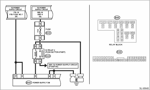
WIRING DIAGRAM:

STEPCHECKYESNO

1.CHECK FUSE.

1) Turn the ignition switch to OFF.

2) Check fuse (FB-18).

Is the fuse blown out?

Replace the fuse (FB-18). If the replaced fuse blows out easily, repair the short circuit in the harness between the fuse and body integrated unit.

2.CHECK WIRING HARNESS.

1) Disconnect the power supply CM connector (B420).

2) Measure the voltage between the power supply CM connector and chassis ground.

Connector & terminal

(B420) No. 12 (+) — Chassis ground (−):

(B420) No. 33 (+) — Chassis ground (−):

Is the voltage 10 V or more?

Repair or replace the open circuit of harness.

3.CHECK HARNESS.

Check continuity between the power supply CM connector and chassis ground.

Connector & terminal

(B420) No. 6 — Chassis ground:

(B420) No. 40 — Chassis ground:

Is there continuity?

Repair the open circuit of harness or replace harness.

4.CHECK IG RELAY 2 (PUSH BUTTON START).

Remove IG relay 2 (push button start), and perform a check.

Is the relay OK?

Replace the relay.

5.CHECK WIRING HARNESS.

Check continuity between the power supply CM connector and the IG relay 2 (push button start) holder.

Connector & terminal

(B420) No. 35 — (B425) No. 38:

Is there continuity?

Repair the open circuit of harness or replace harness.

6.CHECK WIRING HARNESS.

Check continuity between the power supply CM connector and chassis ground.

Connector & terminal

(B425) No. 38 — Chassis ground:

Is there continuity?

Repair the open circuit of harness or replace harness.

7.CHECK WIRING HARNESS.

Check the voltage between the power supply CM connector and chassis ground.

Connector & terminal

(B420) No. 35 (+) — Chassis ground (−):

Is the voltage less than 1 V?

Repair or replace the short circuit of the harness.

8.CHECK POWER SUPPLY CM.

1) Connect the power supply CM connector.

2) Using a tester, measure the voltage between the power supply CM connector and chassis ground when the ignition is turned from OFF to ON.

Connector & terminal

(B420) No. 35 (+) — Chassis ground (−):

Did the voltage change from less than 1 V to +B−2 V or more?

System is normal.

Replace the power supply CM.