DTC DETECTING CONDITION:
Fuse blown, open or short circuit in the harness from the fuse to the power supply CM, or there is a short in the IG system internal circuit of the power supply CM or between the power supply CM and the relay.
TROUBLE SYMPTOM:
• Not all functions operate at ignition ON.
• IG relay 1 (push button start), or IG relay 2 (push button start), accessory relay (push button start) do not operate.
CAUTION:
When the power supply CM is replaced with a new unit, and the battery ground terminal is connected, it will become ignition ON. Also, if the battery is disconnected, it will resume to a condition with the battery cut off.
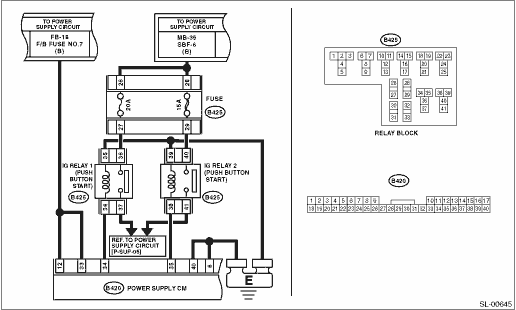
WIRING DIAGRAM:

| STEP | CHECK | YES | NO |
|
Is the fuse blown out? |
Replace the fuse. |
|
|
|
Is the voltage 10 V or more? |
|
Repair the open or shorted circuit of harness. |
|
|
Is there continuity? |
|
Repair the open circuit of harness or replace harness. |
|
|
Is the relay OK? |
|
Replace the relay. |
|
|
Is the relay OK? |
|
Replace the relay. |
|
|
Is there continuity? |
|
Repair or replace the open circuit of harness. |
|
|
1) Connect the power supply CM connector, and attach IG relay 1 (push button start) and IG relay 2 (push button start). 2) Using a tester, measure the voltage between the back of the power supply CM connector and the terminal and chassis ground when the ignition switch is turned from OFF to ON. Connector & terminal (B420) No. 34 (+) — Chassis ground (−): (B420) No. 35 (+) — Chassis ground (−): |
Did the voltage change from 1 V or less to +B−2 V or more? |
System is normal. |
Replace the power supply CM. |
