KEYLESS ACCESS WITH PUSH BUTTON START SYSTEM (DIAGNOSTICS) > Diagnostic Procedure with Diagnostic Trouble Code (DTC)

DTC B2005 SSP SYSTEM COMMUNICATION SUSPENSION DIAGNOSIS (BF)

DTC DETECTING CONDITION:

There is no communication between the remote engine starter and the gateway CM.

TROUBLE SYMPTOM:

The remote engine starter function does not operate.
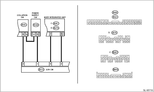
WIRING DIAGRAM:

STEPCHECKYESNO

1.CHECK WIRING HARNESS.

1) Disconnect the collation CM, gateway CM, and power supply CM connectors.

2) Using a tester, check the continuity between the connectors and chassis ground.

Connector & terminal

(B420) No. 7 — Chassis ground:

(B420) No. 24 — Chassis ground:

(B419) No. 12 — Chassis ground:

Is there continuity?

Repair or replace the short circuit of the harness.

2.CHECK WIRING HARNESS.

Using a tester, measure the voltage between the connectors and chassis ground.

Connector & terminal

(B420) No. 7 (+) — Chassis ground (−):

(B420) No. 24 (+) — Chassis ground (−):

(B419) No. 12 (+) — Chassis ground (−):

Is the voltage 5 V or more?

Repair or replace the short circuit of the harness.

3.CHECK REMOTE ENGINE STARTER CIRCUIT.

Check the power supply circuit and ground circuit of the remote engine starter control module.

Are the power supply and ground circuits normal?

Check the fuse, or repair or replace the harness.

4.CHECK REMOTE ENGINE STARTER CIRCUIT.

Using a tester, check continuity between the remote engine starter control module and gateway CM connector.

Connector & terminal

(B419) No. 3 — (B427) No. 1:

Is there continuity?

Replace the remote engine starter control module.

Repair or replace the open circuit of harness.