1.CHECK STARTER MOTOR.
1) Turn the ignition to ON.
2) Check the starter motor condition.
|
Is the starter motor rotating?
|
|
Repair the short circuit to power supply.
NOTE:
In this case, repair the following harnesses:
• Short circuit to power supply in harness between ECM and starter relay connector
• Short circuit to power supply in harness between ECM and starter motor
• Short circuit to power supply in harness between starter relay connector and starter motor
|
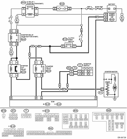
2.CHECK HARNESS BETWEEN STARTER CUT RELAY CONNECTOR AND STARTER RELAY CONNECTOR.
1) Turn the ignition to OFF.
2) Disconnect the connector from starter motor.
3) Remove the starter cut relay and starter relay.
4) Turn the ignition to ON.
5) Measure the voltage between starter relay connector and chassis ground.
Connector & terminal
(B225) No. 9 (+) — Chassis ground (−):
|
Is the voltage 10 V or more?
|
Repair the short circuit to power supply in harness between starter cut relay connector and starter relay connector.
|
|
3.CHECK STARTER CUT RELAY.
1) Connect the battery to starter cut relay terminals No. 1 and No. 3.
2) Measure the resistance between starter cut relay terminals.
|
Is the resistance 1 MΩ or more?
|
|
Replace the starter cut relay. 
|
4.CHECK HARNESS BETWEEN ECM AND STARTER RELAY CONNECTOR.
1) Disconnect the connectors from the ECM.
2) Measure the resistance between ECM and chassis ground.
Connector & terminal
(B136) No. 20 — Chassis ground:
|
Is the resistance 1 MΩ or more?
|
|
Repair the short circuit to ground in harness between ECM and starter relay connector.
|
5.CHECK STARTER RELAY.
Measure the resistance between starter relay terminals.
|
Is the resistance 1 MΩ or more?
|
|
Replace the starter relay.
|
6.CHECK HARNESS BETWEEN ECM, STARTER RELAY CONNECTOR AND STARTER MOTOR.
1) Disconnect the connectors from the ECM.
2) Turn the ignition to ON.
3) Measure the voltage between ECM and chassis ground.
Connector & terminal
(B135) No. 13 (+) — Chassis ground (−):
|
Is the voltage 10 V or more?
|
Repair the short circuit to power supply.
NOTE:
In this case, repair the following harnesses:
• Short circuit to power supply in harness between ECM and starter relay connector
• Short circuit to power supply in harness between ECM and starter motor
• Short circuit to power supply in harness between starter relay connector and starter motor
|
Repair the poor contact of the ECM connector.
|