1.CHECK CURRENT DATA.
2) Read the data of air flow sensor signal using the Subaru Select Monitor or general scan tool.
NOTE:
• Subaru Select Monitor
For detailed operation procedures, refer to “READ CURRENT DATA FOR ENGINE”. 
• General scan tool
For detailed operation procedures, refer to the general scan tool operation manual.
|
Is the voltage less than 0.2 V?
|
|
Even if DTC is detected, the circuit has returned to a normal condition at this time. Reproduce the fault condition, and reperform the check.
NOTE:
In this case, there may be a temporary connector contact failure.
|
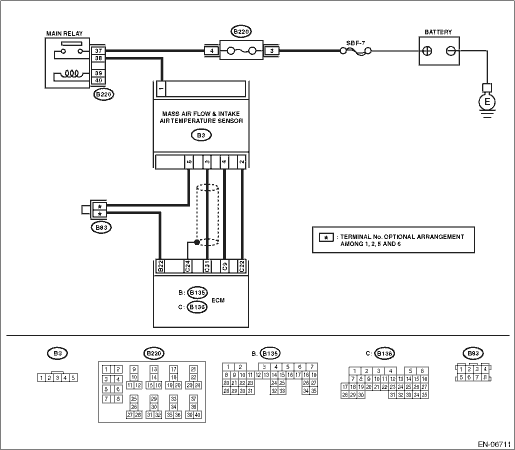
2.CHECK POWER SUPPLY OF MASS AIR FLOW AND INTAKE AIR TEMPERATURE SENSOR.
1) Turn the ignition switch to OFF.
2) Disconnect the connector from the mass air flow and intake air temperature sensor.
3) Turn the ignition switch to ON.
4) Measure the voltage between mass air flow and intake air temperature sensor connector and engine ground.
Connector & terminal
(B3) No. 1 (+) — Engine ground (−):
|
Is the voltage 10 V or more?
|
|
Repair the harness and connector.
NOTE:
In this case, repair the following item:
• Open circuit of harness between the main relay and the mass air flow and intake air temperature sensor connector.
• Poor contact of main relay connector
|
3.CHECK HARNESS BETWEEN ECM AND MASS AIR FLOW AND INTAKE AIR TEMPERATURE SENSOR CONNECTORS.
1) Turn the ignition switch to OFF.
2) Disconnect the connectors from the ECM.
3) Measure the resistance of harness between ECM and mass air flow and intake air temperature sensor connectors.
Connector & terminal
(B136) No. 31 — (B3) No. 3:
|
Is the resistance less than 1 Ω?
|
|
Repair the open circuit of harness between the ECM and mass air flow and intake air temperature sensor connectors.
|
4.CHECK HARNESS BETWEEN ECM AND MASS AIR FLOW AND INTAKE AIR TEMPERATURE SENSOR CONNECTORS.
Measure the resistance between ECM and chassis ground.
Connector & terminal
(B136) No. 31 — Chassis ground:
|
Is the resistance 1 MΩ or more?
|
|
Repair the ground short circuit of harness between the ECM and the mass air flow and intake air temperature sensor connectors.
|
5.CHECK FOR POOR CONTACT.
Check for any poor contact in the ECM or the mass air flow and intake air temperature sensor connectors.
|
Is there poor contact in the ECM or the mass air flow and intake air temperature sensor connectors?
|
Repair any poor contact between the ECM and the mass air flow and intake air temperature sensor connectors.
|
Replace the mass air flow and intake air temperature sensor.
|