ENGINE (DIAGNOSTICS)(H4DO) > Diagnostic Procedure with Diagnostic Trouble Code (DTC)

DTC P1521 BRAKE SWITCH CIRCUIT RANGE

DTC DETECTING CONDITION:

Detected when two consecutive driving cycles with fault occur.

CAUTION:

After repairing or replacing the defective part, perform the Clear Memory Mode and Inspection Mode .
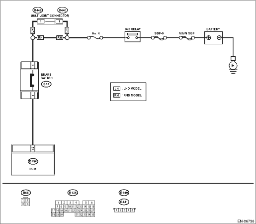
WIRING DIAGRAM:

STEPCHECKYESNO

1.CHECK INPUT SIGNAL OF ECM.

1) Turn the ignition switch to ON.

2) Measure the voltage between ECM and chassis ground with the brake pedal depressed.

Connector & terminal

(B136) No. 12 (+) — Chassis ground (−):

Is the voltage 10 V or more?

Repair the poor contact of the ECM connector.

2.CHECK BRAKE SWITCH.

1) Turn the ignition switch to OFF.

2) Disconnect the brake switch connector.

3) Measure the resistance of the brake switch connectors with the brake pedal depressed.

Terminals

No. 1 — No. 4:

Is the resistance less than 1 Ω?

Replace the brake switch.

3.CHECK HARNESS BETWEEN ECM AND BRAKE SWITCH.

1) Disconnect the connectors from the ECM.

2) Measure the resistance of harness between ECM and brake switch connector.

Connector & terminal

(B136) No. 12 — (B65) No. 1:

Is the resistance less than 1 Ω?

Repair open circuit in harness between ECM and brake switch connector.

4.CHECK HARNESS BETWEEN ECM AND BRAKE SWITCH.

Measure the resistance between ECM and chassis ground.

Connector & terminal

(B136) No. 12 — Chassis ground:

Is the resistance 1 MΩ or more?

Repair the short circuit to ground harness between ECM and brake switch connector.

5.CHECK BRAKE SWITCH POWER SUPPLY.

1) Turn the ignition switch to ON.

2) Measure the voltage between brake pedal switch and chassis ground.

Connector & terminal

(B65) No. 4 (+) — Chassis ground (−):

Is the voltage 10 V or more?

Repair the poor contact of brake switch connector.

NOTE:

Check the following item and repair or replace if necessary.

Open circuit in power supply circuit

Short circuit to ground in power supply circuit

Blown out of fuse (No. 4)