|
Description |
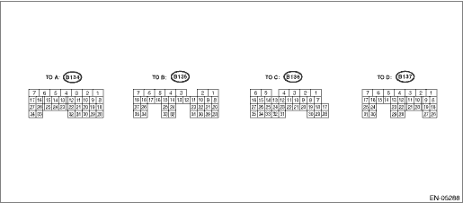
Connector No. |
Terminals No. |
Signal (V) |
Reference | ||
|
Ignition SW ON (engine OFF) |
Engine ON (idling) | |||||
|
Crankshaft position sensor |
Signal (+) |
B137 |
29 |
0 |
−7 — +7 |
Waveform |
|
Signal (−) |
B137 |
30 |
0 |
0 |
— | |
|
Shield |
B137 |
21 |
0 |
0 |
— | |
|
Rear oxygen sensor |
Signal |
B137 |
18 |
0 |
0 — 0.9 |
— |
|
Shield |
B137 |
27 |
0 |
0 |
— | |
|
Ground (sensor) |
B134 |
29 |
0 |
0 |
— | |
|
Front oxygen (A/F) sensor heater |
Signal 1 |
B134 |
2 |
0 — 1.0 |
— |
Waveform |
|
Signal 2 |
B134 |
1 | ||||
|
Rear oxygen sensor heater signal |
B134 |
5 |
0 — 1.0 |
— |
Waveform | |
|
Engine coolant temperature sensor |
Signal |
B137 |
11 |
1.0 — 1.4 |
1.0 — 1.4 |
After engine is warmed up. |
|
Ground (sensor) |
B134 |
29 |
0 |
0 |
After engine is warmed up. | |
|
Air flow sensor |
Signal |
B136 |
31 |
— |
0.3 — 4.5 |
— |
|
Shield |
B136 |
24 |
0 |
0 |
— | |
|
Ground |
B136 |
22 |
0 |
0 |
— | |
|
Intake air temperature sensor signal |
B136 |
9 |
0.3 — 4.6 |
0.3 — 4.6 |
— | |
|
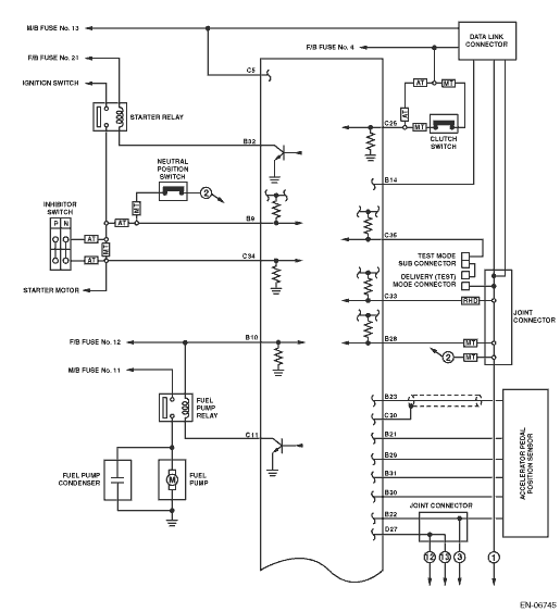
Starter switch |
B136 |
34 |
0 |
0 |
Model without push button start Cranking: 8 — 14 Model with push button start Cranking: waveform | |
|
Starter switch 2 |
B135 |
20 |
0 |
0 |
Model with push button start Cranking: 8 — 14 | |
|
Starter cut relay |
B135 |
33 |
0 |
0 |
Model with push button start Cranking: 8 — 14 | |
|
Accessory cut request |
B135 |
34 |
10 — 13 |
12 — 14 |
Model with push button start Cranking: 0 | |
|
Starter relay |
B135 |
32 |
ON: 0 OFF: 10 — 13 |
ON: 0 OFF: 12 — 14 |
— | |
|
A/C switch |
B136 |
26 |
ON: 10 — 13 OFF: 0 |
ON: 12 — 14 OFF: 0 |
— | |
|
Ignition switch |
B135 |
10 |
10 — 13 |
12 — 14 |
— | |
|
Neutral position switch |
B135 |
9 |
ON: 0 OFF: 10 — 13 |
ON: 0 OFF: 12 — 14 |
• For AT model, switch is ON when select lever is shifted into “P” range or “N” range. • For MT model, switch is ON when select lever is shifted into “N” range. | |
|
Delivery (test) mode connector |
B136 |
35 |
10 — 13 |
12 — 14 |
When connected: 0 | |
|
Knock sensor |
Signal |
B134 |
9 |
2.8 |
2.8 |
— |
|
Shield |
B134 |
20 |
0 |
0 |
— | |
|
Back-up power supply |
B136 |
5 |
10 — 13 |
12 — 14 |
Ignition switch “OFF”: 10 — 13 | |
|
Control module power supply |
B136 |
3 |
10 — 13 |
12 — 14 |
— | |
|
B136 |
4 |
10 — 13 |
12 — 14 |
— | ||
|
Sensor power supply |
B134 |
28 |
5 |
5 |
— | |
|
Ignition control |
#1 |
B134 |
11 |
0 |
0 — 5 |
Waveform |
|
#2 |
B134 |
12 |
0 |
0 — 5 |
Waveform | |
|
#3 |
B134 |
21 |
0 |
0 — 5 |
Waveform | |
|
#4 |
B134 |
22 |
0 |
0 — 5 |
Waveform | |
|
Fuel injector |
#1 |
B134 |
15 |
10 — 13 |
1 — 14 |
Waveform |
|
#2 |
B134 |
16 |
10 — 13 |
1 — 14 |
Waveform | |
|
#3 |
B134 |
25 |
10 — 13 |
1 — 14 |
Waveform | |
|
#4 |
B134 |
26 |
10 — 13 |
1 — 14 |
Waveform | |
|
Fuel pump relay control |
B136 |
11 |
ON: 0.5 or less OFF: 10 — 13 |
0.5 or less |
— | |
|
A/C relay control |
B135 |
24 |
ON: 0.5 or less OFF: 10 — 13 |
ON: 0.5 or less OFF: 12 — 14 |
— | |
|
Radiator fan relay 1 control |
B135 |
19 |
ON: 0.5 or less OFF: 10 — 13 |
ON: 0.5 or less OFF: 12 — 14 |
— | |
|
Radiator fan relay 2 control |
B135 |
27 |
ON: 0.5 or less OFF: 10 — 13 |
ON: 0.5 or less OFF: 12 — 14 |
Model with A/C only | |
|
Self-shutoff control |
B135 |
15 |
10 — 13 |
12 — 14 |
— | |
|
AT/MT identification signal |
B135 |
28 |
0 |
0 |
MT model only | |
|
Steering wheel switch signal |
B136 |
33 |
0 |
0 |
RHD model only | |
|
Malfunction indicator light |
B135 |
16 |
— |
— |
Light “ON”: 1 or less Light “OFF”: 10 — 14 | |
|
Engine speed output |
B135 |
25 |
— |
0 — 13 or more |
Waveform | |
|
Purge control solenoid valve |
B134 |
8 |
ON: 1 or less OFF: 10 — 13 |
ON: 1 or less OFF: 12 — 14 |
Waveform | |
|
EGR valve |
Signal A+ |
B134 |
23 |
0 or 10 — 13 |
0 or 12 — 14 |
— |
|
Signal A− |
B134 |
24 |
0 or 10 — 13 |
0 or 12 — 14 |
— | |
|
Signal B+ |
B134 |
13 |
0 or 10 — 13 |
0 or 12 — 14 |
— | |
|
Signal B− |
B134 |
14 |
0 or 10 — 13 |
0 or 12 — 14 |
— | |
|
Manifold absolute pressure sensor |
Signal |
B137 |
15 |
3.8 — 4.4 |
1.2 — 2.5 |
— |
|
Power supply |
B134 |
28 |
5 |
5 | ||
|
Ground (sensor) |
B134 |
29 |
0 |
0 | ||
|
A/C middle pressure switch |
B136 |
15 |
ON: 0 OFF: 4.5 — 5.5 |
ON: 0 OFF: 4.5 — 5.5 |
— | |
|
Front oxygen (A/F) sensor |
Signal (+) |
B137 |
23 |
1.2 — 3.2 |
1.2 — 3.2 |
— |
|
Signal (−) |
B137 |
14 |
1.2 — 2.7 |
1.2 — 2.7 |
— | |
|
Shield |
B137 |
31 |
0 |
0 |
— | |
|
SSM/GST communication line |
B135 |
14 |
1← → 4 |
1← → 4 |
— | |
|
Ground (injector) |
B134 |
7 |
0 |
0 |
— | |
|
Ground (power supply) |
B134 |
6 |
0 |
0 |
— | |
|
B135 |
5 |
0 |
0 |
— | ||
|
Ground (control system) |
B135 |
3 |
0 |
0 |
— | |
|
B135 |
4 |
0 |
0 |
— | ||
|
Ground (front oxygen (A/F) sensor heater 1) |
B134 |
3 |
0 |
0 |
— | |
|
Ground (front oxygen (A/F) sensor heater 2) |
B134 |
4 |
0 |
0 |
— | |
|
Intake camshaft position sensor (LH) |
B137 |
13 |
0 — 0.9 |
ON: 0 OFF: 4.7 — 5.3 |
Waveform | |
|
Intake camshaft position sensor (RH) |
B137 |
12 |
0 — 0.9 |
ON: 0 OFF: 4.7 — 5.3 |
Waveform | |
|
Electronic throttle control |
Main |
B134 |
19 |
0.4 — 0.7 Fully opened: 4.0 — 4.7 |
0.4 — 0.7 (After engine is warmed up.) |
— |
|
Sub |
B134 |
18 |
4.2 — 4.8 Fully opened: 0.1 — 0.3 |
4.2 — 4.8 (After engine is warmed up.) |
— | |
|
Shield |
B137 |
27 |
0 |
0 |
— | |
|
Power supply |
B134 |
28 |
5 |
5 |
— | |
|
Ground (sensor) |
B134 |
29 |
0 |
0 |
— | |
|
Electronic throttle control motor 1 (+) |
B137 |
3 |
Duty waveform |
Duty waveform |
Drive frequency: 500 Hz | |
|
Electronic throttle control motor 2 (+) |
B137 |
2 |
Duty waveform |
Duty waveform |
Drive frequency: 500 Hz | |
|
Electronic throttle control motor 1 (−) |
B137 |
5 |
Duty waveform |
Duty waveform |
Drive frequency: 500 Hz | |
|
Electronic throttle control motor 2 (−) |
B137 |
4 |
Duty waveform |
Duty waveform |
Drive frequency: 500 Hz | |
|
Electronic throttle control motor power supply 1 |
B136 |
1 |
10 — 13 |
12 — 14 |
— | |
|
Electronic throttle control motor power supply 2 |
B136 |
2 |
10 — 13 |
12 — 14 |
— | |
|
Ground (electronic throttle control motor 1) |
B137 |
6 |
0 |
0 |
— | |
|
Ground (electronic throttle control motor 2) |
B137 |
7 |
0 |
0 |
— | |
|
Electronic throttle control motor relay |
B135 |
6 |
0 |
0 |
Ignition switch “ON”: ON | |
|
Oil flow control solenoid (LH) |
Signal |
B134 |
34 |
Duty waveform |
Duty waveform |
— |
|
Oil flow control solenoid (RH) |
Signal |
B134 |
33 |
Duty waveform |
Duty waveform |
— |
|
Accelerator pedal position sensor (main) |
Signal |
B135 |
23 |
Fully closed: 1 Fully opened: 3.0 or more |
Fully closed: 1 Fully opened: 3.0 or more |
— |
|
Power supply |
B135 |
29 |
5 |
5 |
— | |
|
Ground (sensor) |
B135 |
21 |
0 |
0 |
— | |
|
Shield |
B136 |
30 |
0 |
0 |
— | |
|
Accelerator pedal position sensor (sub) |
Signal |
B135 |
31 |
Fully closed: 1 Fully opened: 3.0 or more |
Fully closed: 1 Fully opened: 3.0 or more |
— |
|
Power supply |
B135 |
30 |
5 |
5 |
— | |
|
Ground (sensor) |
B135 |
22 |
0 |
0 |
— | |
|
Clutch switch |
B136 |
25 |
When clutch pedal is depressed: 0 When clutch pedal is released: 10 — 13 |
When clutch pedal is depressed: 0 When clutch pedal is released: 12 — 14 |
— | |
|
Brake switch 1 |
B136 |
12 |
When brake pedal is depressed: 0 When brake pedal is released: 10 — 13 |
When brake pedal is depressed: 0 When brake pedal is released: 12 — 14 |
— | |
|
Brake switch 2 |
B136 |
13 |
When brake pedal is depressed: 10 — 13 When brake pedal is released: 0 |
When brake pedal is depressed: 12 — 14 When brake pedal is released: 0 |
— | |
|
Cruise control main switch |
B136 |
14 |
ON: 0 OFF: 5 |
ON: 0 OFF: 5 |
— | |
|
Cruise control command switch |
B136 |
23 |
When operating nothing: 3.5 — 4.5 When operating RES/ACC: 2.5 — 3.5 When operating SET/COAST: 0.5 — 1.5 When operating cancel: 0 — 0.5 |
When operating nothing: 3.5 — 4.5 When operating RES/ACC: 2.5 — 3.5 When operating SET/COAST: 0.5 — 1.5 When operating cancel: 0 — 0.5 |
— | |
|
CAN communication |
Signal (+) |
B135 |
1 |
Pulse signal |
— | |
|
Signal (−) |
B135 |
2 |
Pulse signal |
— | ||
|
Immobilizer |
Signal 1 |
B135 |
11 |
Less than 1 ←→ more than 4 |
Less than 1 ←→ more than 4 |
— |
|
Signal 2 |
B135 |
12 |
Less than 1 ←→ more than 4 |
Less than 1 ←→ more than 4 |
— | |
|
generator control |
B135 |
17 |
0 — 6.5 |
0 — 6.5 |
— | |
|
Input/output name |
Measuring condition |
Waveform |
|
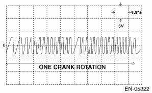
1. Crankshaft position sensor |
At idling |
|
|
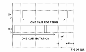
2. Camshaft position sensor |
At idling |
|
• Model without push button start
• Model with push button start
|
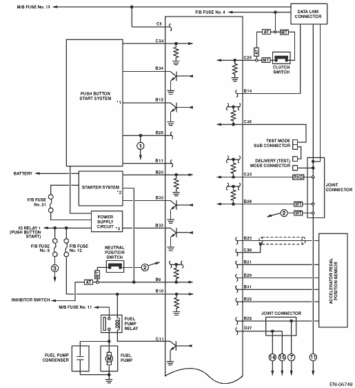
*1 |
Refer to “Push Button Start System” in Wiring System. |
|
*2 |
Refer to “Starter System” in Wiring System. |
|
*3 |
Refer to “Power Supply Circuit” in Wiring System. |