ENGINE (DIAGNOSTICS)(H4DOTC DIESEL) > Diagnostic Procedure with Diagnostic Trouble Code (DTC)
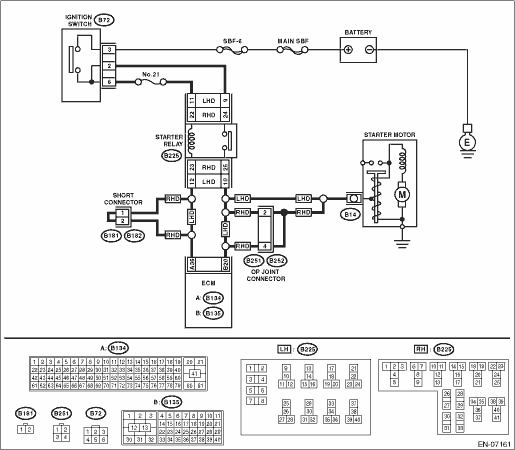
1. MODEL WITHOUT PUSH BUTTON START
DTC DETECTING CONDITION:
Immediately at fault recognition
TROUBLE SYMPTOM:
Failure of engine to start
CAUTION:
After servicing or replacing faulty parts, perform Clear Memory Mode  and Inspection Mode .
WIRING DIAGRAM:
1.CHECK FOR ANY OTHER DTC ON DISPLAY.
|
Is any other DTC displayed?
|
Check the appropriate DTC using the “List of Diagnostic Trouble Code (DTC)”.
|
|
2.CHECK HARNESS BETWEEN ECM AND IGNITION SWITCH.
1) Turn the ignition switch to OFF.
2) Disconnect the connector from ECM.
3) Turn the ignition switch to ON.
4) Measure the voltage between ECM connector and chassis ground.
Connector & terminal
(B135) No. 20 (+) — Chassis ground (−):
|
Is the voltage 10 V or more?
|
Repair the short circuit to power supply in harness between ECM connector and ignition switch.
|
Repair the poor contact of ECM connector.
|
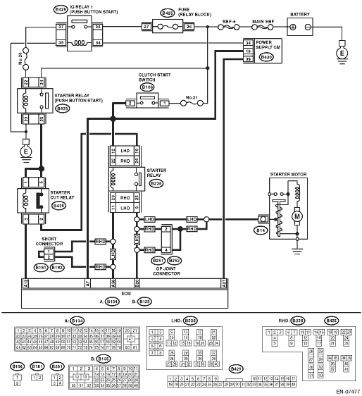
2. MODEL WITH PUSH BUTTON START
DTC DETECTING CONDITION:
Immediately at fault recognition
TROUBLE SYMPTOM:
Failure of engine to start
CAUTION:
After servicing or replacing faulty parts, perform Clear Memory Mode and Inspection Mode .
WIRING DIAGRAM:

1.CHECK STARTER MOTOR.
1) Turn the ignition to ON.
2) Check the starter motor condition.
|
Is the starter motor rotating?
|
|
Repair the short circuit to power supply.
NOTE:
In this case, repair the following harnesses:
• Short circuit to power supply in harness between ECM connector and starter relay connector
• Short circuit to power supply in harness between ECM connector and starter motor
• Short circuit to power supply in harness between starter relay connector and starter motor
|
2.CHECK HARNESS BETWEEN STARTER CUT RELAY CONNECTOR AND STARTER RELAY CONNECTOR.
1) Turn the ignition to OFF.
2) Disconnect the connector from starter motor.
3) Remove the starter cut relay and starter relay.
4) Turn the ignition to ON.
5) Measure the voltage between starter relay connector and chassis ground.
Connector & terminal
LHD model
(B225) No. 10 (+) — Chassis ground (−):
RHD model
(B225) No. 24 (+) — Chassis ground (−):
|
Is the voltage 10 V or more?
|
Repair the short circuit to power supply in harness between starter cut relay connector and starter relay connector.
|
|
3.CHECK STARTER CUT RELAY.
1) Connect the battery to starter cut relay terminals No. 1 and No. 3.
2) Measure the resistance between starter cut relay terminals.
|
Is the resistance 1 MΩ or more?
|
|
Replace the starter cut relay.
|
4.CHECK HARNESS BETWEEN ECM AND STARTER RELAY CONNECTOR.
1) Disconnect the connector from ECM.
2) Measure the resistance between ECM connector and chassis ground.
Connector & terminal
(B134) No. 36 — Chassis ground:
|
Is the resistance 1 MΩ or more?
|
|
Repair the short circuit to ground in harness between ECM connector and starter relay connector.
|
5.CHECK STARTER RELAY.
Measure the resistance between starter relay terminals.
Terminals
LHD model
No. 9 — No. 10:
RHD model
No. 24 — No. 25:
|
Is the resistance 1 MΩ or more?
|
|
Replace the starter relay.
|
6.CHECK HARNESS BETWEEN ECM, STARTER RELAY CONNECTOR AND STARTER MOTOR.
1) Disconnect the connector from ECM.
2) Turn the ignition to ON.
3) Measure the voltage between ECM connector and chassis ground.
Connector & terminal
(B135) No. 20 (+) — Chassis ground (−):
|
Is the voltage 10 V or more?
|
Repair the short circuit to power supply.
NOTE:
In this case, repair the following harnesses:
• Short circuit to power supply in harness between ECM connector and starter relay connector
• Short circuit to power supply in harness between ECM connector and starter motor
• Short circuit to power supply in harness between starter relay connector and starter motor
|
Repair the poor contact of ECM connector.
|