CAUTION:
After servicing or replacing faulty parts, perform Clear Memory Mode  , and Inspection Mode .
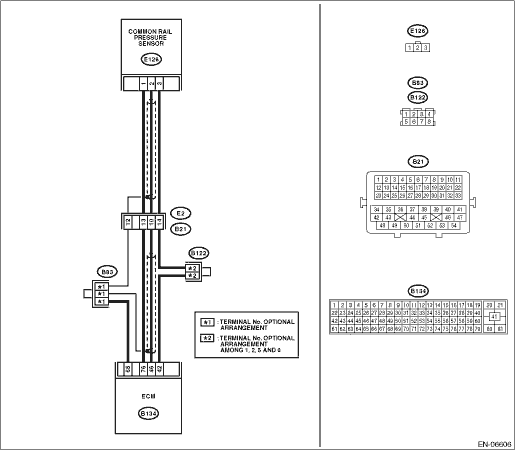
WIRING DIAGRAM:

1. COMMON RAIL PRESSURE INSPECTION PROCEDURE WHEN ENGINE IS COLD
CAUTION:
This inspection must be completed quickly before the engine coolant temperature reaches 60°C (140°F).
1. Turn off all the electric load.
2. In “Current Data Display & Save” on the Subaru Select Monitor, display the following items using the “data select display”.
|
Item |
Unit |
|
Coolant Temp. |
°C or °F |
|
Engine Speed |
rpm |
|
Common rail pressure |
kPa, mmHg, inHg, or psig |
|
Target Common Rail Pressure |
kPa, mmHg, inHg, or psig |
NOTE:
• If the “data select display” is not used, the measurement accuracy is degraded and correct measurement results cannot be obtained.
• Perform the measurement on the “digital data screen”.
• For detailed operation procedures, refer to “PC application help for Subaru Select Monitor”.
3. Start the engine when “Coolant Temp.” is less than 60°C (140°F), and measure each engine speed in Table 1 for approximately 10 seconds and save the measurement data.
If the “Common rail pressure” data at each engine speed is within the range shown in Table 1, it is normal.
NOTE:
• Perform the measurement quickly so that the “Coolant Temp.” does not become high.
• Examine the measurement data on the “Graph2 screen”. When doing so, change the range as necessary in order to examine the data in more detail.
• In Table 1, the actual “Target Common Rail Pressure” measurement value at each engine speed is shown as A, B, or C respectively.
|
Item |
Engine speed | ||
|
Idling (Accelerator opening: 0%) |
2,000 rpm (Accelerator opening: Constant) |
4,000 rpm (Accelerator opening: Constant) | |
|
Common rail pressure (kPa) |
A±3,000 |
B±3,000 |
C±3,000 |
|
Target Common Rail Pressure (kPa) |
A |
B |
C |
4. Start the engine when “Coolant Temp.” is less than 60°C (140°F), and measure each engine speed range in Table 2 three times consecutively and save the measurement data.
When the measurement is finished for all the engine speed ranges, repeat the measurement again and save the measurement data.
If the “Common rail pressure” data in each engine speed range is within the range shown in Table 2, it is normal.
NOTE:
• Perform the measurement quickly so that the “Coolant Temp.” does not become high.
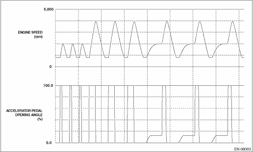
• After keeping the accelerator pedal in the released state, bring the engine speed to the target speed with the accelerator opened to 100%. When the target speed is reached, release the accelerator pedal.
• Except when keeping the 2,000 rpm state, operate the accelerator pedal rapidly.
• Examine the measurement data on the “Graph2 screen”. When doing so, change the range as necessary in order to examine the data in more detail.
• In Table 2, the actual “Target Common Rail Pressure” measurement value in each engine speed range is shown as A, B, or C respectively.
Measurement image
|
Item |
Engine speed range | ||
|
Idling → 2,000 rpm (Accelerator opening: 0 → 100%) |
Idling → 4,000 rpm (Accelerator opening: 0 → 100%) |
2,000 → 4,000 rpm (Accelerator opening: Constant → 100%) | |
|
Common rail pressure (kPa) |
≥ 20,000 and ≤ max. of A + 20,000 ≥ min. of A − 15,000 |
≥ 20,000 and ≤ max. of B + 20,000 ≥ min. of B − 15,000 |
≥ 20,000 and ≤ max. of C + 20,000 ≥ min. of C − 15,000 |
|
Target Common Rail Pressure (kPa) |
A |
B |
C |
2. COMMON RAIL PRESSURE INSPECTION PROCEDURE WHEN ENGINE IS WARM
1. Turn off all the electric load.
2. Perform the fuel pump compulsory learning mode.
3. In “Current Data Display & Save” on the Subaru Select Monitor, display the following items using the “data select display”.
|
Item |
Unit |
|
Coolant Temp. |
°C or °F |
|
Engine Speed |
rpm |
|
Common rail pressure |
kPa, mmHg, inHg, or psig |
|
Target Common Rail Pressure |
kPa, mmHg, inHg, or psig |
NOTE:
• If the “data select display” is not used, the measurement accuracy is degraded and correct measurement results cannot be obtained.
• Perform the measurement on the “digital data screen”.
• For detailed operation procedures, refer to “PC application help for Subaru Select Monitor”.
4. Measure each engine speed in Table 3 for approximately 10 seconds and save the measurement data.
If the “Common rail pressure” data at each engine speed is within the range shown in Table 3, it is normal.
NOTE:
• Examine the measurement data on the “Graph2 screen”. When doing so, change the range as necessary in order to examine the data in more detail.
• In Table 3, the actual “Target Common Rail Pressure” measurement value at each engine speed is shown as A, B, or C respectively.
|
Item |
Engine speed | ||
|
Idling (Accelerator opening: 0%) |
2,000 rpm (Accelerator opening: Constant) |
4,000 rpm (Accelerator opening: Constant) | |
|
Common rail pressure (kPa) |
A±3,000 |
B±3,000 |
C±3,000 |
|
Target Common Rail Pressure (kPa) |
A |
B |
C |
NOTE:
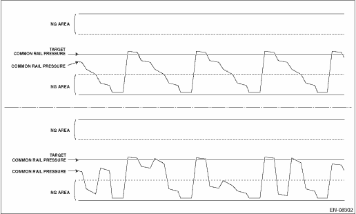
If the Common rail pressure is significantly below the lower limit of the Target Common Rail Pressure, with a waveform with cyclic down movements, the fuel pump needs to be replaced.
5. Measure each engine speed range in Table 4 three times consecutively and save the measurement data.
When the measurement is finished for all the engine speed ranges, repeat the measurement again and save the measurement data.
If the “Common rail pressure” data in each engine speed range is within the range shown in Table 4, it is normal.
NOTE:
• After keeping the accelerator pedal in the released state, bring the engine speed to the target speed with the accelerator opened to 100%. When the target speed is reached, release the accelerator pedal.
• Except when keeping the 2,000 rpm state, operate the accelerator pedal rapidly.
• Examine the measurement data on the “Graph2 screen”. When doing so, change the range as necessary in order to examine the data in more detail.
• In Table 4, the actual “Target Common Rail Pressure” measurement value in each engine speed range is shown as A, B, or C respectively.
Measurement image
|
Item |
Engine speed range | ||
|
Idling → 2,000 rpm (Accelerator opening: 0 → 100%) |
Idling → 4,000 rpm (Accelerator opening: 0 → 100%) |
2,000 → 4,000 rpm (Accelerator opening: Constant → 100%) | |
|
Common rail pressure (kPa) |
≥ 20,000 and ≤ max. of A + 20,000 ≥ min. of A − 15,000 |
≥ 20,000 and ≤ max. of B + 20,000 ≥ min. of B − 15,000 |
≥ 20,000 and ≤ max. of C + 20,000 ≥ min. of C − 15,000 |
|
Target Common Rail Pressure (kPa) |
A |
B |
C |