1. Install the valve rocker assembly.
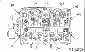
(1) Temporarily tighten the bolts equally in alphabetical order as shown in the figure.
NOTE:
• Do not temporarily tighten the bolts (i) and (j).
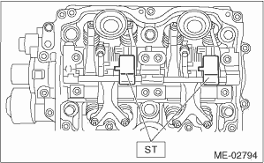
• Set the ST in the position shown in the drawing to mount the intake valve rocker assembly.
| ST 18354AA000 | VALVE ROCKER HOLDER |
(2) Tighten the bolts (a) through (h) to specified torque.
Tightening torque:
25 N·m (2.5 kgf-m, 18.4 ft-lb)
(3) Tighten the bolts (i) through (j) to specified torque.
Tightening torque:
6 N·m (0.6 kgf-m, 4.3 ft-lb)
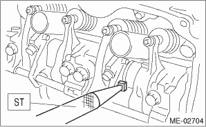
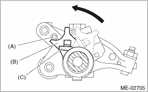
(4) Use the ST to rotate the spring stopper in the direction of the arrow to fasten the adjuster pin.
| ST 18258AA000 | SPRING INSTALLER |
|
(A) |
Adjuster pin |
|
(B) |
Spring stopper |
|
(C) |
Spring |
2. Adjust the valve clearance. 
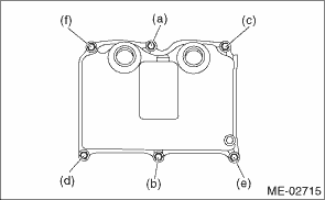
3. Install the rocker cover.
(1) Install the rocker cover gasket to the rocker cover.
NOTE:
Use a new rocker cover gasket.
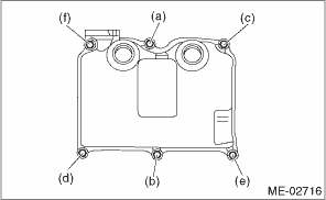
(2) Temporarily tighten the bolts in alphabetical sequence as shown in figure, then tighten the bolt in 2 steps.
Tightening torque:
1st
6.4 N·m (0.7 kgf-m, 4.7 ft-lb)
2nd (only (a) and (b) are tightened)
6.4 N·m (0.7 kgf-m, 4.7 ft-lb)
RH side
LH side
4. Connect the PCV hose.
5. Install the high tension cord.
6. Install the timing belt cover.