1. PURGE CONTROL SOLENOID VALVE 1
Install in the reverse order of removal.
NOTE:
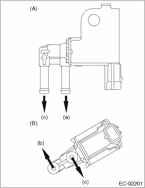
Connect the evaporation hose as shown in the figure.
|
(A) |
Purge control solenoid valve 1 |
|
(B) |
Purge control solenoid valve 2 |
|
(a) |
To intake manifold |
|
(b) |
To intake duct |
|
(c) |
To branch pipe and fuel pipe |
Tightening torque:
6.4 N·m (0.7 kgf-m, 4.7 ft-lb)
2. PURGE CONTROL SOLENOID VALVE 2
Install in the reverse order of removal.
NOTE:
Connect the evaporation hose as shown in the figure.
|
(A) |
Purge control solenoid valve 1 |
|
(B) |
Purge control solenoid valve 2 |
|
(a) |
To intake manifold |
|
(b) |
To intake duct |
|
(c) |
To branch pipe and fuel pipe |
Tightening torque:
6.4 N·m (0.7 kgf-m, 4.7 ft-lb)
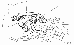
Tightening torque:
T1: 17 N·m (1.7 kgf-m, 12.5 ft-lb)
T2: 19 N·m (1.9 kgf-m, 14.0 ft-lb)