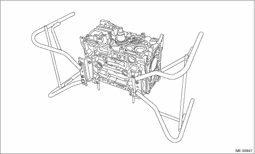
1. After setting the cylinder block to ST, install the crankshaft bearing.
| ST 499817100 | ENGINE STAND |
NOTE:
Apply a coat of engine oil to the bearing and crankshaft journal.
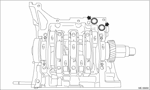
2. Mount the crankshaft in cylinder block (LH).
3. Install O-rings to the cylinder block (LH).
NOTE:
Use new O-rings.
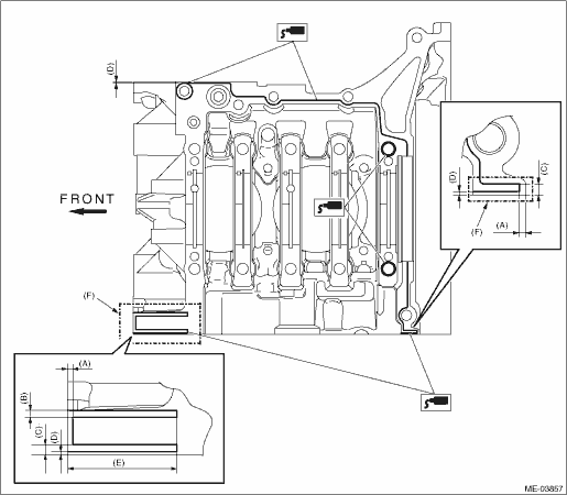
4. Apply liquid gasket to the mating surface of cylinder block (RH) as shown in the figure.
CAUTION:
Do not allow liquid gasket to run over into oil passages, bearing grooves, etc.
NOTE:
Install within 5 min. after applying liquid gasket.
Liquid gasket:
THREE BOND 1217G (Part No. K0877Y0100) or equivalent
Liquid gasket applying diameter:
Outside dotted line (F) area
1.0±0.5 mm (0.0394±0.0197 in)
Inside dotted line (F) area
3.0±0.5 mm (0.1181±0.0197 in)
|
(A) |
2.5 mm (0.0984 in) |
(C) |
3.5 mm (0.1378 in) |
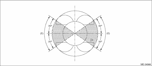
(E) |
55 mm (2.1654 in) |
|
(B) |
3.0 mm (0.1181 in) |
(D) |
1.0 mm (0.0394 in) |
5. Attach cylinder block (RH) to cylinder block (LH).
6. Join the cylinder blocks.
(1) Apply a coat of engine oil to the seal washers and bolt threads.
NOTE:
• Use a new seal washer.
• To prevent mixture of engine oil into the water jacket, do not apply a large amount.
(2) Tighten all bolts with a torque of 10 N·m (1.0 kgf-m, 7.4 ft-lb) in the numerical sequence as shown in the figure.
(3) Tighten all bolts with a torque of 45 N·m (4.5 kgf-m, 33.2 ft-lb) in the numerical sequence as shown in the figure.
(4) Loosen all bolts by 360° in the reverse order as shown in the figure.
(5) Tighten all bolts with a torque of 15 N·m (1.5 kgf-m, 11.1 ft-lb) in the numerical sequence as shown in the figure.
(6) Tighten all bolts with a torque of 23 N·m (2.3 kgf-m, 17.0 ft-lb) in the numerical sequence as shown in the figure.
(7) Tighten all bolts again with a torque of 23 N·m (2.3 kgf-m, 17.0 ft-lb) in the numerical sequence as shown in the figure.
(8) Tighten all bolts by 90° in numerical order as shown in the figure.
CAUTION:
The tightening angle of the bolt should not exceed 90°.
(9) Tighten bolts (1) — (6) bolts by 45° in numerical order as shown in the figure.
CAUTION:
The tightening angle of the bolt should not exceed 45°.
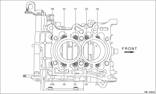
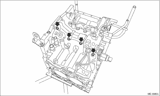
(10) Install the upper bolt to cylinder block.
Tightening torque:
25 N·m (2.5 kgf-m, 18.4 ft-lb)
NOTE:
Remove any liquid gasket squeezed out onto the seal surface between the chain cover and oil pan upper, after tightening the cylinder block connecting bolts.
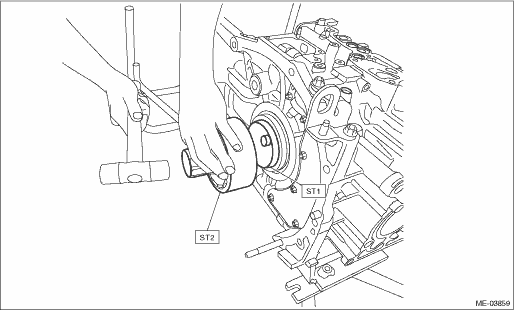
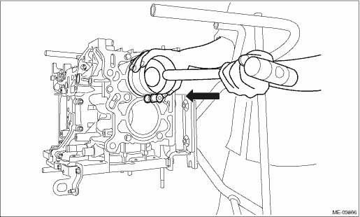
7. Apply a coat of engine oil to the oil seal periphery, then install the rear oil seal using ST1 and ST2.
NOTE:
Use a new rear oil seal.
| ST1 499597100 | CRANKSHAFT OIL SEAL GUIDE |
| ST2 499587200 | CRANKSHAFT OIL SEAL INSTALLER |
8. Face the front of the engine up, standing the engine on one end.
9. Attach the piston ring and oil ring to the piston.
CAUTION:
• Make sure ring gaps do not face the same direction.
• Assemble the top ring so that the taper surface faces towards the top of the piston.
• Assemble so that the stamp mark faces towards the top of the piston.
(1) Position the top ring gap at (A) in the figure.
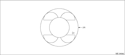
(2) Position the second ring gap at (B).
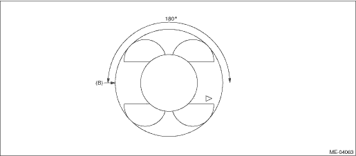
(3) Set the rail gap to position (C) of the figure.
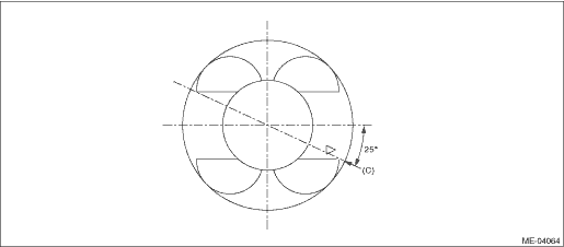
(4) Position the expander gap at (D) in the figure.
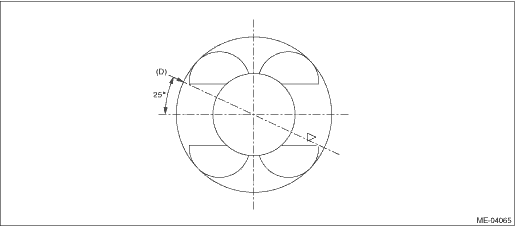
(5) Check that the ring gap of the top ring, second ring, and oil ring is within the range indicated in figure (E).
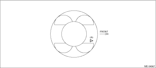
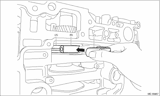
10. Install the #1 piston and connecting rod to the cylinder block.
(1) Apply engine oil to the outer circumference of the piston and in the cylinder block.
(2) Face the front mark of the piston (A) towards the front of the engine, and insert the piston into the cylinder block.
NOTE:
When inserting the piston into the cylinder block, perform according to the items listed below.
• Use a commercially sold piston ring compressor.
• Insert while lightly tapping the crown of the piston with the handle of a plastic hammer.
• Insert while making sure that the large end of the connecting rod does not scratch the cylinder liner.
• Insert while continually making sure that the large end of the connecting rod does not touch the crankshaft and cylinder block.
|
(A) |
#1 connecting rod |
(B) |
#1 crank pin |
(3) Using the ST, turn the crankshaft and match the positions of the crank pin and the large end of the connecting rod.
| ST 18252AA000 | CRANKSHAFT SOCKET |
(4) Tighten the connecting rod cap bolt at 20 N·m (2.0 kgf-m, 14.8 ft-lb).
NOTE:
Always use new connecting rod cap bolts.
(5) Further tighten the connecting rod cap bolts by 120° — 125°.
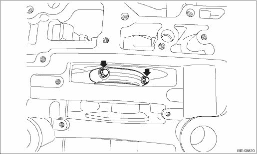
|
(A) |
#1 connecting rod |
(B) |
#1 crank pin |
(C) |
#1 connecting rod cap |
11. In the same procedures as for the #1 piston, install the piston and connecting rods to the cylinder block, in the order of #2, #3, and #4.
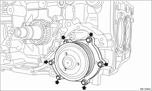
12. Install the water pump.
NOTE:
Use a new gasket.
Tightening torque:
6.4 N·m (0.7 kgf-m, 4.7 ft-lb)
13. Select the cylinder head gasket.
NOTE:
Be sure to perform cylinder head gasket selection when the following work has been performed.
• Cylinder block replacement
• Crankshaft replacement
• Connecting rod replacement
• Piston replacement
• Crankshaft bearing replacement
• Connecting rod bearing replacement
(1) Clean the mating surface with the cylinder head.
(2) Using a dial gauge and magnet, use the cylinder head mating surface as the reference point.
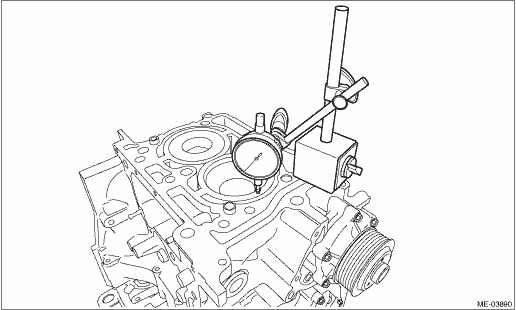
(3) Using the ST, turn the crankshaft and set the piston to TDC.
| ST 18252AA000 | CRANKSHAFT SOCKET |
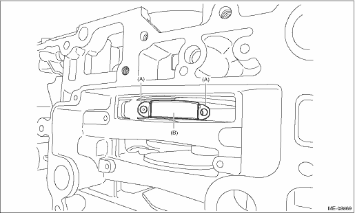
(4) Measure the amount of piston protrusion from the cylinder block end face
Amount of piston protrusion from the cylinder block end face:
Minimum value
0.200 mm (0.0079 in)
Maximum value
0.400 mm (0.0157 in)
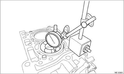
NOTE:
• Perform the measurement of piston protrusion for the #1 and #3 pistons simultaneously, and for the #2 and #4 pistons simultaneously.
• Measure in 2 locations for each piston, and from an average value calculated from 4 points of the cylinders on one side, select the gasket.
• Turn the ST clockwise and counterclockwise, and the largest value indicated on the dial gauge is the measured value.
• The illustration shows #2 and #4 pistons.
• Perform the measurement using the same procedures and locations for #1 and #3 pistons.
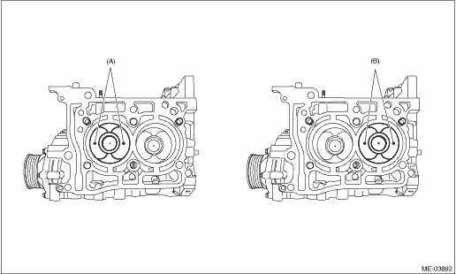
|
(A) |
#2 piston measurement point |
(B) |
#4 piston measurement point |
(5) Average the measurements taken from the 4 points, and select the cylinder head gasket from the table below.
• Cylinder head gasket (LH)
|
Piston protrusion |
Part No. |
Thickness |
Grade |
Number of identification holes |
|
0.200 mm (0.0079 in) — 0.275 mm (0.0108 in) |
10944AA040 |
0.95 mm (0.0374 in) |
A |
1 |
|
0.275 mm (0.0108 in) — 0.325 mm (0.0128 in) |
10944AA030 |
1.00 mm (0.0394 in) |
B |
2 |
|
0.325 mm (0.0128 in) — 0.400 mm (0.0157 in) |
10944AA050 |
1.05 mm (0.0413 in) |
C |
3 |
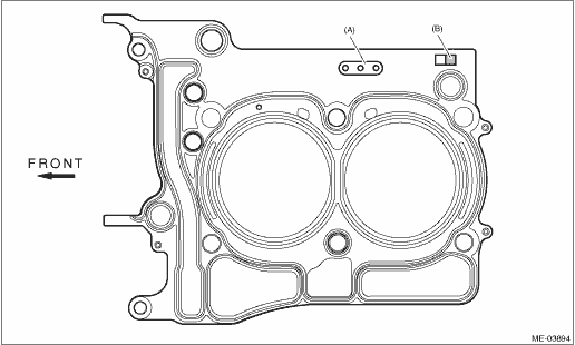
|
(A) |
Cylinder head gasket (LH) identification hole |
(B) |
Grade |
• Cylinder head gasket (RH)
|
Piston protrusion |
Part No. |
Thickness |
Grade |
Number of identification holes |
|
0.200 mm (0.0079 in) — 0.275 mm (0.0108 in) |
11044AA740 |
0.95 mm (0.0374 in) |
A |
1 |
|
0.275 mm (0.0108 in) — 0.325 mm (0.0128 in) |
11044AA730 |
1.00 mm (0.0394 in) |
B |
2 |
|
0.325 mm (0.0128 in) — 0.400 mm (0.0157 in) |
11044AA750 |
1.05 mm (0.0413 in) |
C |
3 |
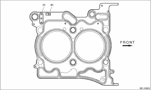
|
(A) |
Cylinder head gasket (RH) identification holes |
(B) |
Grade |
14. Attach the engine oil cooler. 
15. Install the oil pump.
16. Install the oil pan upper and strainer.
17. Install the oil pan.
18. Install the common rail assembly.
19. Install the fuel pump.
20. Install the fuel pump gear.
21. Install the cylinder head.
22. Install the camshaft.
23. Attach the fuel delivery pipe and return pipe.
24. Install the rocker cover.
25. Attach the A/C compressor.
26. Install the generator.
27. Install the intake manifold.
28. Install the cam sprocket.
NOTE:
Step 28 is only performed when the cam sprocket is removed.
29. Install the timing chain assembly.
30. Install the chain cover.
31. Attach the oil level gauge and oil level gauge guide to the chain cover.
32. Install the camshaft position sensor.
33. Install the vacuum pump.
34. Install the scavenger pump.
35. Install the crank pulley.
36. Install the V-belt tensioner.
37. Install the V-belts.
38. Install the engine to the vehicle.