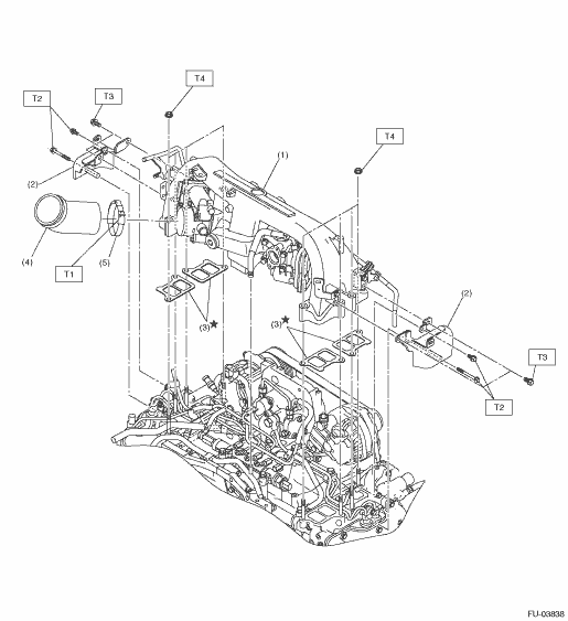
• Installation location
|
(1) |
Intake manifold |
(4) |
Air duct hose |
Tightening torque:N·m (kgf-m, ft-lb) | |
|
(2) |
Intake manifold protector |
(5) |
Clamp |
T1: |
5 (0.5, 3.7) |
|
(3) |
Gasket |
T2: |
6.4 (0.7, 4.7) | ||
|
T3: |
19 (1.9, 14.0) | ||||
|
T4: |
25 (2.5, 18.4) | ||||
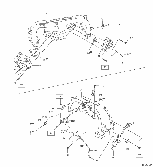
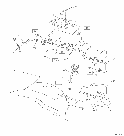
• Intake manifold
|
(1) |
Intake manifold |
(10) |
By-pass air pipe |
(19) |
O-ring |
|
(2) |
Air breather hose stay |
(11) |
Vacuum hose |
(20) |
Stud bolt |
|
(3) |
Gasket |
(12) |
Boost control valve |
||
|
(4) |
EGR control valve |
(13) |
Vacuum hose |
Tightening torque:N·m (kgf-m, ft-lb) | |
|
(5) |
Gasket |
(14) |
Solenoid valve damper |
T1: |
3.5 (0.4, 2.6) |
|
(6) |
Throttle body |
(15) |
Clip |
T2: |
6.4 (0.7, 4.7) |
|
(7) |
Manifold absolute pressure and intake air temperature sensor |
(16) |
Vacuum hose |
T3: |
8 (0.8, 5.9) |
|
(8) |
By-pass air pipe |
(17) |
Vacuum hose stay |
T4: |
13 (1.3, 9.6) |
|
(9) |
Vacuum hose |
(18) |
Air conditioner hose bracket |
T5: |
19 (1.9, 14.0) |
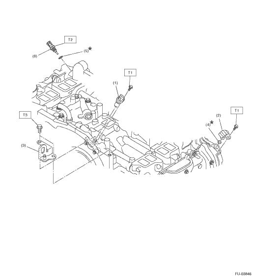
2. CRANKSHAFT POSITION SENSOR, CAMSHAFT POSITION SENSOR, ENGINE COOLANT TEMPERATURE SENSOR
|
(1) |
Crankshaft position sensor |
(4) |
O-ring |
Tightening torque:N·m (kgf-m, ft-lb) | |
|
(2) |
Camshaft position sensor |
(5) |
Gasket |
T1: |
6.4 (0.7, 4.7) |
|
(3) |
Engine hanger |
(6) |
Engine coolant temperature sensor |
T2: |
18 (1.8, 13.3) |
|
T3: |
19 (1.9, 14.0) | ||||
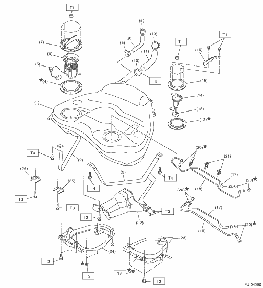
|
(1) |
Fuel tank |
(12) |
Fuel sub level sensor gasket |
(23) |
Fuel tank protector LH |
|
(2) |
Fuel tank band RH |
(13) |
Filter |
(24) |
Fuel tank protector RH |
|
(3) |
Fuel tank band LH |
(14) |
Fuel sub level sensor |
(25) |
Stopper LH |
|
(4) |
Fuel level sensor gasket |
(15) |
Fuel sub level sensor plate upper |
(26) |
Stopper RH |
|
(5) |
Fuel level sensor |
(16) |
Fuel sub level sensor protector |
||
|
(6) |
Fuel level sensor case ASSY |
(17) |
Fuel sub delivery tube |
Tightening torque:N·m (kgf-m, ft-lb) | |
|
(7) |
Fuel level sensor plate upper |
(18) |
Fuel return tube (LHD model) |
T1: |
4.4 (0.4, 3.2) |
|
(8) |
Clip |
(19) |
Fuel delivery tube (RHD model) |
T2: |
9 (0.9, 6.6) |
|
(9) |
Air vent hose |
(20) |
Retainer |
T3: |
18 (1.8, 13.3) |
|
(10) |
Clamp |
(21) |
Tube clamp |
T4: |
33 (3.4, 24.3) |
|
(11) |
Fuel filler hose |
(22) |
Heat shield cover |
T5: |
2 (0.2, 1.5) |
4. SUB FUEL PUMP, FUEL DAMPER, TWO-WAY VALVE
|
(1) |
Clamp |
(9) |
Fuel hose |
(17) |
Sub fuel pump bracket B |
|
(2) |
Fuel hose |
(10) |
Clip |
||
|
(3) |
Fuel damper ASSY |
(11) |
Hose |
Tightening torque:N·m (kgf-m, ft-lb) | |
|
(4) |
Fuel hose |
(12) |
Two-way valve |
T1: |
1.25 (0.1, 0.9) |
|
(5) |
Sub fuel pump |
(13) |
Drain hose |
T2: |
7.5 (0.8, 5.5) |
|
(6) |
Sub fuel pump bracket A |
(14) |
Clamp bracket |
T3: |
8.5 (0.9, 6.3) |
|
(7) |
Fuel hose |
(15) |
Hose clamp |
T4: |
1.5 (0.2, 1.1) |
|
(8) |
Fuel damper |
(16) |
Clamp |
T5: |
7.35 (0.7, 5.4) |
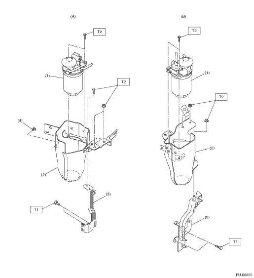
• Installation location
|
(A) |
LHD model |
(B) |
RHD model |
||
|
(1) |
Fuel filter ASSY |
(3) |
Fuel filter lower bracket |
Tightening torque:N·m (kgf-m, ft-lb) | |
|
(2) |
Fuel filter protector |
(4) |
Harness clip (LHD model only) |
T1: |
13 (1.3, 9.6) |
|
T2: |
18 (1.8, 13.3) | ||||
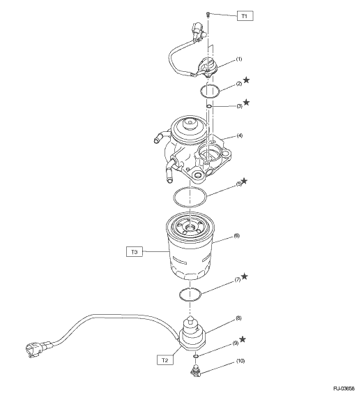
• Exploded view
|
(1) |
Heater switch |
(6) |
Fuel filter |
Tightening torque:N·m (kgf-m, ft-lb) | |
|
(2) |
O-ring |
(7) |
O-ring |
T1: |
2 (0.2, 1.5) |
|
(3) |
O-ring |
(8) |
Sedimentor level switch |
T2: |
4.9 (0.5, 3.6) |
|
(4) |
Priming pump ASSY |
(9) |
O-ring |
T3: |
17.2 (1.8, 12.7) |
|
(5) |
O-ring |
(10) |
Drain plug |
||
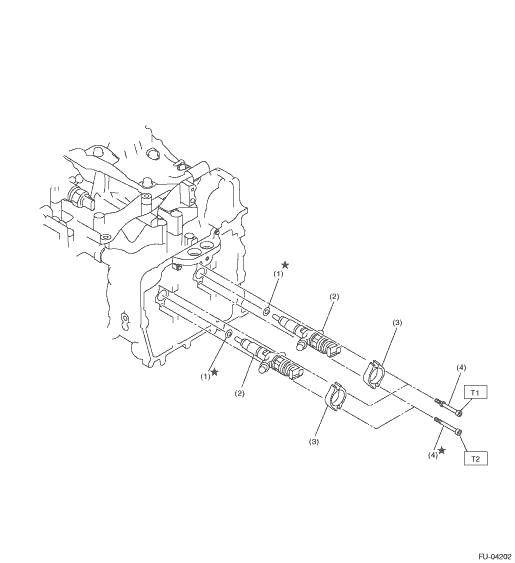
|
(1) |
Gasket |
(3) |
Fuel injector holder |
Tightening torque:N·m (kgf-m, ft-lb) | |
|
(2) |
Fuel injector |
(4) |
Bolt |
T1: |
7.7 (0.8, 5.7) |
|
T2: |
| ||||

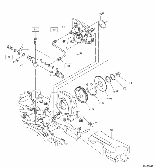
7. FUEL PUMP, FUEL PUMP GEAR, COMMON RAIL ASSEMBLY
|
(1) |
Gasket |
(7) |
Noise cushion |
Tightening torque:N·m (kgf-m, ft-lb) | |
|
(2) |
Fuel return pipe |
(8) |
Snap ring |
T1: |
19 (1.9, 14.0) |
|
(3) |
Common rail ASSY |
(9) |
Washer |
T2: |
20 (2.0, 14.8) |
|
(4) |
Fuel delivery pipe |
(10) |
Sub gear |
T3: |
35 (3.6, 25.8) |
|
(5) |
Fuel pump |
(11) |
Spring |
T4: |
63.7 (6.5, 47.0) |
|
(6) |
O-ring |
(12) |
Fuel pump gear |
||
|
(1) |
Fuel pipe holder |
(10) |
Clamp |
(18) |
Fuel return pipe (RHD model) |
|
(2) |
Fuel return pipe (LHD model) |
(11) |
Fuel hose (LHD model) |
(19) |
Fuel return pipe (LHD model) |
|
(3) |
Fuel pipe holder stay |
(12) |
Fuel pipe (LHD model) |
||
|
(4) |
Cap |
(13) |
Gasket |
Tightening torque:N·m (kgf-m, ft-lb) | |
|
(5) |
Fuel delivery pipe (No. 2) |
(14) |
Fuel pipe (RHD model) |
T1: |
1.25 (0.1, 0.9) |
|
(6) |
Fuel delivery pipe (No. 4) |
(15) |
Fuel hose (RHD model) |
T2: |
6.4 (0.7, 4.7) |
|
(7) |
Fuel delivery pipe (No. 1) |
(16) |
Fuel pipe (RHD model) |
T3: |
17 (1.7, 12.5) |
|
(8) |
Fuel delivery pipe (No. 3) |
(17) |
Fuel hose (RHD model) |
T4: |
35 (3.6, 25.8) |
|
(9) |
Fuel pipe |
||||
|
(1) |
Fuel pipe |
(11) |
Fuel hose (RHD model) |
(21) |
Fuel hose (LHD model) |
|
(2) |
Clamp |
(12) |
Fuel delivery pipe |
(22) |
Fuel hose |
|
(3) |
Fuel hose |
(13) |
Gasket |
(23) |
Fuel return pipe (LH) |
|
(4) |
Fuel return pipe (LHD model) |
(14) |
Fuel return pipe (RH) |
||
|
(5) |
Fuel pipe (LHD model) |
(15) |
Fuel return pipe (RH) |
Tightening torque:N·m (kgf-m, ft-lb) | |
|
(6) |
Fuel hose (LHD model) |
(16) |
Fuel pipe protector |
T1: |
1.25 (0.1, 0.9) |
|
(7) |
Clip |
(17) |
Fuel return pipe (LH) |
T2: |
6.4 (0.7, 4.7) |
|
(8) |
Fuel hose (RHD model) |
(18) |
Gasket |
T3: |
12.5 (1.3, 9.2) |
|
(9) |
Fuel return pipe (RHD model) |
(19) |
Fuel delivery pipe |
T4: |
19 (1.9, 14.0) |
|
(10) |
Fuel pipe (RHD model) |
(20) |
Fuel pipe (RHD model) |
T5: |
20 (2.0, 14.8) |
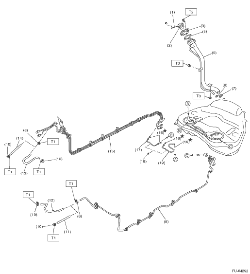
|
(1) |
Tether |
(9) |
Fuel pipe ASSY |
(17) |
Fuel tube (LHD model) |
|
(2) |
Fuel filler cap |
(10) |
Clamp |
(18) |
Clamp |
|
(3) |
Filler ring |
(11) |
Fuel hose (LHD model) |
(19) |
Fuel tube (RHD model) |
|
(4) |
Filler pipe gasket |
(12) |
Fuel hose (RHD model) |
||
|
(5) |
Fuel filler pipe ASSY |
(13) |
Fuel hose (LHD model) |
Tightening torque:N·m (kgf-m, ft-lb) | |
|
(6) |
Clip |
(14) |
Fuel hose (RHD model) |
T1: |
1.25 (0.1, 0.9) |
|
(7) |
Clamp |
(15) |
Fuel and brake pipe ASSY |
T2: |
4.5 (0.5, 3.2) |
|
(8) |
Clamp |
(16) |
Retainer |
T3: |
7.5 (0.8, 5.5) |
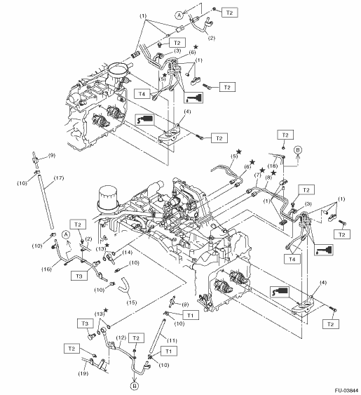
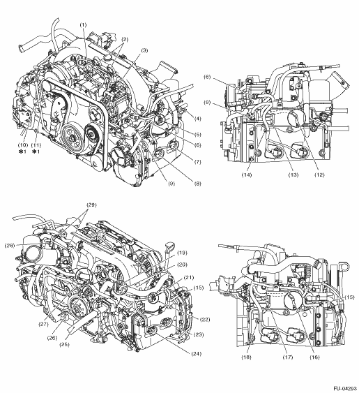
• Structural diagram 1
|
(1) |
Boost control valve |
|
(2) |
Securely install the engine harness clips to the vacuum pipe stay. |
|
(3) |
Manifold absolute pressure and intake air temperature sensor |
|
(4) |
Oil pressure switch |
|
(5) |
Securely install the engine harness clip to the intake manifold protector. |
|
(6) |
Glow docking connector |
|
(7) |
Fuel injector (#4) |
|
(8) |
Fuel injector (#2) |
|
(9) |
Engine coolant temperature sensor |
|
(10) |
Exhaust temperature sensor 1 |
|
(11) |
Exhaust temperature sensor 2 |
|
(12) |
Glow plug (#4) |
|
(13) |
Glow plug (#2) |
|
(14) |
Securely install the engine harness clip to the rocker cover. |
|
(15) |
Camshaft position sensor |
|
(16) |
Glow plug (#1) |
|
(17) |
Glow plug (#3) |
|
(18) |
Securely install the engine harness clip to the rocker cover. |
|
(19) |
EGR control valve |
|
(20) |
Insert the harness connected to the EGR control valve to the underside of the air breather hose. |
|
(21) |
Route the harness connected to the camshaft position sensor under the vacuum hose. |
|
(22) |
Securely install the engine harness clip to the intake manifold protector. |
|
(23) |
Fuel injector (#1) |
|
(24) |
Fuel injector (#3) |
|
(25) |
Body harness |
|
(26) |
Crankshaft position sensor |
|
(27) |
Securely install the engine harness clips to the engine coolant pipe. (two locations) |
|
(28) |
Throttle position sensor |
|
(29) |
Securely install the engine harness clips to the air breather pipe. |
|
*1: When reusing the engine harness, remove and install the harness and the oil level gauge guide as a set. | |
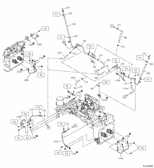
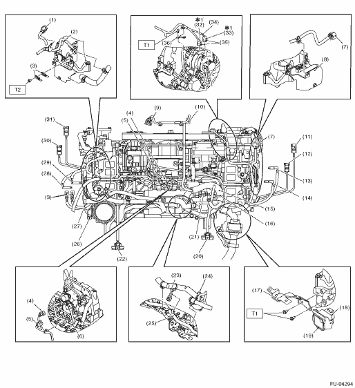
• Structural diagram 2
|
(1) |
Docking connector (Attach the harness connector securely onto the stay lock.) | |
|
(2) |
By-pass air pipe | |
|
(3) |
Engine ground | |
|
(4) |
Suction control valve | |
|
(5) |
Fuel temperature sensor | |
|
(6) |
Fuel pipe | |
|
(7) |
Camshaft position sensor | |
|
(8) |
Intake manifold protector | |
|
(9) |
Manifold absolute pressure and intake air temperature sensor | |
|
(10) |
Boost control valve | |
|
(11) |
Fuel injector (#1) | |
|
(12) |
Fuel injector (#3) | |
|
(13) |
Glow plug (#1) | |
|
(14) |
Glow plug (#3) | |
|
(15) |
Route the engine harness above the fuel pipe. | |
|
(16) |
Install the engine harness clip to the fuel return pipe stay. | |
|
(17) |
Engine harness stay | |
|
(18) |
Docking connector | |
|
(19) |
Securely install the harness connector to the lock part of the engine harness stay. | |
|
(20) |
EGR control valve | |
|
(21) |
Common rail pressure sensor | |
|
(22) |
Throttle position sensor | |
|
(23) |
Crankshaft position sensor | |
|
(24) |
EGR control valve | |
|
(25) |
Water pipe | |
|
(26) |
Oil pressure switch | |
|
(27) |
Route the engine ground under the engine harness. | |
|
(28) |
Glow plug (#4) | |
|
(29) |
Glow plug (#2) | |
|
(30) |
Fuel injector (#4) | |
|
(31) |
Fuel injector (#2) | |
|
(32) |
Exhaust temperature sensor 1 | |
|
(33) |
Exhaust temperature sensor 2 | |
|
(34) |
Yellow marking | |
|
(35) |
Securely install the harness connector to the stay lock part of the oil level gauge guide. | |
|
(36) |
Install the engine harness stay while pushing the stay against the generator bracket. | |
|
*1: When reusing the engine harness, remove and install the harness and the oil level gauge guide as a set. | ||
|
Tightening torque:N·m (kgf-m, ft-lb) |
||
|
T1: |
6.4 (0.7, 4.7) |
|
|
T2: |
19 (1.9, 14.0) |
|