CAUTION:
• When installing the common rail assembly, always replace the fuel delivery pipes with new parts.
• Make sure that water, oil and other foreign matter does not get into the common rail pressure sensor connector.
1. Temporarily tighten the common rail assembly.
2. Install the fuel injectors to the cylinder head and temporarily tighten the bolts. 
3. Install the fuel delivery pipes and fuel return pipes, and temporarily tighten the nuts and bolts.
4. Tighten the fuel pipe holder stay bolts.
Tightening torque:
6.4 N·m (0.7 kgf-m, 4.7 ft-lb)

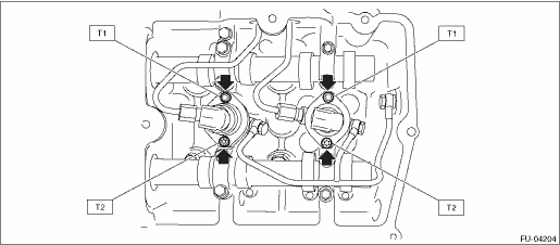
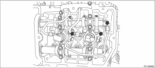
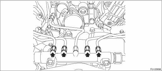
5. Tighten the fuel injector bolts.
CAUTION:
• Always start tightening from the upper bolts first.
• Be careful not to overtighten the lower bolts.
Tightening torque:
T1: 7.7 N·m (0.8 kgf-m, 5.7 ft-lb)
T2: Tighten to 3.5 N·m (0.4 kgf-m, 2.6 ft-lb) of torque, and then tighten a further 85° — 95°
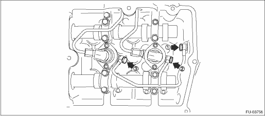
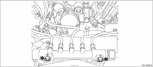
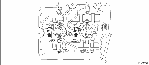
6. Tighten the fuel return pipe union screws.
NOTE:
Tighten in order starting from where joined with the cylinder head and moving towards the front of the engine.
Tightening torque:
12.5 N·m (1.3 kgf-m, 9.2 ft-lb)
7. Make sure there are no air leaks from fuel return pipe joints.
(1) Connect an air pressure gauge to the fuel return pipe on top of the engine to create the circuit shown in the figure below, and apply 250 kPa (2.5 kg-cm2) of air pressure.
CAUTION:
Always use the specified air pressure. If air pressure is too high, air will enter the high-pressure pipe.
NOTE:
Check each side individually.
Circuit Figure
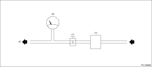
|
(A) |
Engine (To fuel return pipe) |
(B) |
Air pressure gauge |
(C) |
Gate valve |
|
(D) |
Pressure regulator |
|
(A) |
LH side |
(B) |
RH side |
(2) Close the gate valve, maintain air pressure for 60 seconds, and verify that there is no leakage from fuel return pipe joints.
NOTE:
• Apply engine oil to fuel return pipe joints and check for bubbles indicating air leakage.
• Check that the air pressure gauge indicator does not move downward.
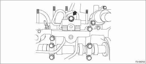
8. Tighten the common rail assembly bolts.
NOTE:
Start tightening from the bolt on the common rail pressure sensor side.
Tightening torque:
19 N·m (1.9 kgf-m, 14.0 ft-lb)
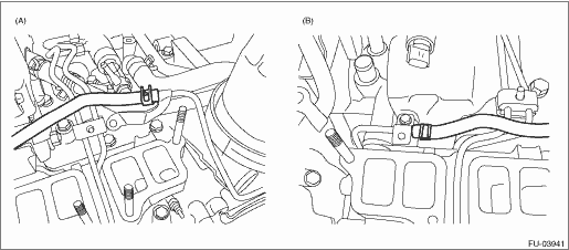
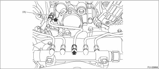
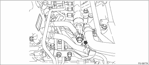
9. Tighten the fuel delivery pipe nuts between the fuel pump and common rail assembly.
CAUTION:
Be careful not to apply an unbalanced load when tightening.
NOTE:
Perform the work while fixing the holder (A) in figure below with a spanner.
Tightening torque:
35 N·m (3.6 kgf-m, 25.8 ft-lb)
10. Tighten the fuel pipe holder bolts.
Tightening torque:
6.4 N·m (0.7 kgf-m, 4.7 ft-lb)
11. Tighten the fuel delivery pipes of the fuel injectors.
Tightening torque:
35 N·m (3.6 kgf-m, 25.8 ft-lb)
12. Tighten the fuel delivery pipe nuts of the common rail assembly.
Tightening torque:
35 N·m (3.6 kgf-m, 25.8 ft-lb)
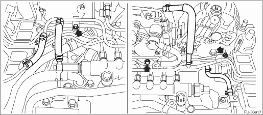
13. Install the fuel pipe.
NOTE:
Use a new gasket.
Tightening torque:
T1: 6.4 N·m (0.7 kgf-m, 4.7 ft-lb)
T2: 17 N·m (1.7 kgf-m, 12.5 ft-lb)
• LHD model
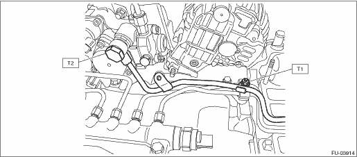
• RHD model
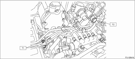
14. Install the fuel return pipes.
Tightening torque:
6.4 N·m (0.7 kgf-m, 4.7 ft-lb)
• LHD model
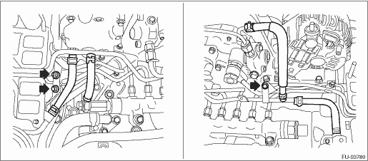
• RHD model
15. Install the fuel return pipe of the pressure limiter.
NOTE:
Use a new gasket.
Tightening torque:
20 N·m (2.0 kgf-m, 14.8 ft-lb)
16. For the remaining parts, install in the reverse order of removal.
17. Install the intake manifold.
18. Install the engine to the vehicle.
19. Pump the priming pump on top of the fuel filter assembly to fill the fuel system with fuel.
NOTE:
Pump the priming pump until it is stiff.
20. If the common rail assembly is replaced, perform compulsory learning mode.
21. Check for fuel leakage.