1. Check the hoses and pipes for deformation, cracks and damage.
2. Perform “High Pressure Fuel Inspection” using the Subaru Select Monitor. 
3. Perform the high pressure fuel inspection and visually check for fuel leakage in the fuel system.
4. Check the engine oil amount.
If the engine oil amount has increased abnormally or the smell of diesel is present, continue to the following procedure.
5. Check for fuel leakage in the fuel return pipes inside the rocker cover.
If there are no faults, replace the fuel delivery pipe.
1. FUEL RETURN PIPE FUEL LEAKAGE CHECK
WARNING:
Place “NO OPEN FLAMES” signs near the working area.
CAUTION:
• Be careful not to spill fuel.
• Catch the fuel from hoses and pipes using a container or cloth.
1. Disconnect the ground cable from battery.
2. Remove the collector cover.
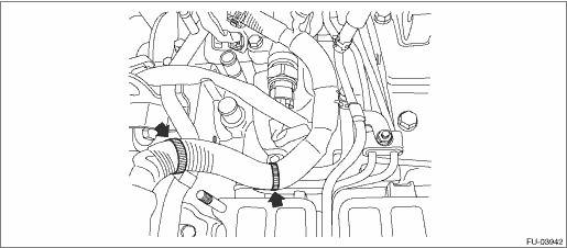
3. Disconnect the fuel return hose from the fuel pump.
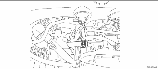
4. Disconnect the vehicle fuel return hose and plug so that it is airtight.
NOTE:
The figure show a LHD model. Position for a RHD model is on the reverse side.
5. Connect an air pressure gauge to the fuel return hose of the disconnected fuel pump to create the circuit shown in the figure below, and apply 250 kPa (2.5 kg-cm2) of air pressure.
CAUTION:
Always use the specified air pressure. If air pressure is too high, air will enter the high-pressure pipe.
Circuit Figure
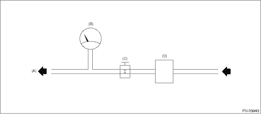
|
(A) |
Engine (To fuel return pipe) |
(B) |
Air pressure gauge |
(C) |
Gate valve |
|
(D) |
Pressure regulator |
6. Close the valve, maintain air pressure for 60 seconds, and verify that the air pressure gauge indicator does not move downward.
NOTE:
If the air pressure gauge indicator moves downward, continue to the following procedure.
7. Install the fuel return hose to fuel pump.
8. Remove the intake manifold.
9. Remove the clip holding the engine harness from each pipe. (RHD model)
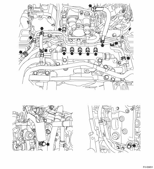
10. Disconnect the fuel return hoses from the fuel return pipes.
NOTE:
Check each side individually.
• LH side
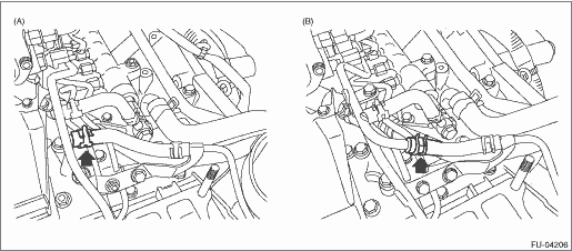
|
(A) |
LHD model |
(B) |
RHD model |
• RH side
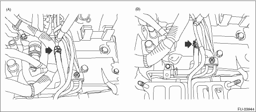
|
(A) |
LHD model |
(B) |
RHD model |
11. Connect an air pressure gauge to the disconnected fuel return hose to create the circuit shown in the figure below, and apply 250 kPa (2.5 kg-cm2) of air pressure.
CAUTION:
Always use the specified air pressure. If air pressure is too high, air will enter the high-pressure pipe.
Circuit Figure
|
(A) |
Engine (To fuel return pipe) |
(B) |
Air pressure gauge |
(C) |
Gate valve |
|
(D) |
Pressure regulator |
12. Close the valve, maintain air pressure for 60 seconds, and verify that the air pressure gauge indicator does not move downward.
NOTE:
Check that the air pressure gauge indicator does not move downward for both right and left sides.
13. Remove the engine from vehicle.
14. Remove the rocker cover of the side for which the air pressure gauge indicator moves downward.
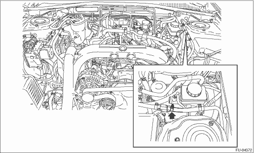
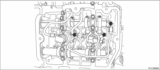
15. Connect an air pressure gauge to the hose of the fuel return pipe on top of the engine to create the circuit shown in the figure below, and apply 250 kPa (2.5 kg-cm2) of air pressure.
CAUTION:
Always use the specified air pressure. If air pressure is too high, air will enter the high-pressure pipe.
16. Close the valve, maintain air pressure for 60 seconds, and verify that there is no leakage from fuel return pipe joints.
NOTE:
Apply engine oil to fuel return pipe joints and check for bubbles indicating air leakage.
17. Change the gasket of any part that has an air leak.
18. Install parts in the reverse order of removal.