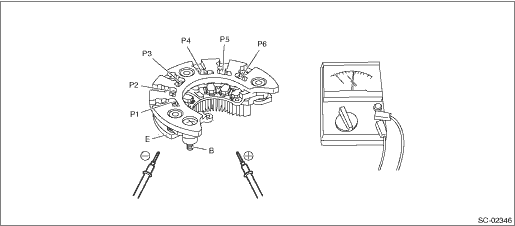
CAUTION:
There is the possibility of damaging the diodes if a mega-tester (used to measure high voltages) or a similar measuring instrument is used. Never use a mega tester or equivalent for this test.
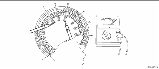
1. Check for continuity between the diode lead and terminal E or B. If continuity is not as shown in the table, replace the rectifier.
• At analog type tester
|
Tester lead |
Continuity | |
|
−lead |
+lead | |
|
E |
P1, P2, P3, P4, P5, P6 |
Yes |
|
B |
No | |
|
P1, P2, P3, P4, P5, P6 |
E |
No |
|
B |
Yes | |
• At digital type tester
|
Tester lead |
Continuity | |
|
−lead |
+lead | |
|
E |
P1, P2, P3, P4, P5, P6 |
No |
|
B |
Yes | |
|
P1, P2, P3, P4, P5, P6 |
E |
Yes |
|
B |
No | |
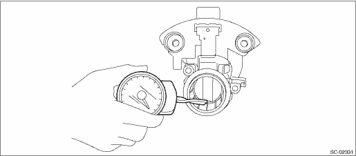
1. Slip ring surface
Inspect the slip rings for contamination or any roughness on the sliding surface. Repair the slip ring surface using a lathe or sand paper.
2. Slip ring outer diameter
Measure the slip ring outer diameter. Replace the rotor assembly if the slip ring is worn.
Slip ring outer diameter:
Standard
22.7 mm (0.8937 in)
Service limit
22.1 mm (0.8701 in)
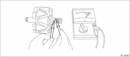
3. Continuity test
Using a circuit tester, check the resistance between slip rings. If the resistance is not within the standard, replace the rotor assembly.
Specified resistance:
Approximately 2.0 — 2.4 Ω
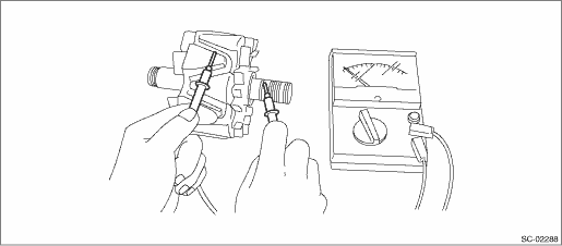
4. Insulation test
Check the continuity between slip ring and rotor core or shaft. If there is continuity, replace the rotor assembly because the rotor coil is grounded.
5. Bearing (rear side)
Check the bearing (rear side). If there is any noise, or the rotor does not rotate smoothly, replace the bearings.
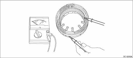
1. Continuity test
Inspect the continuity between the stator coil terminals. If continuity is not as shown in the table, replace the stator coil.
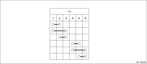
|
(A) |
Terminal |
2. Insulation test
Inspect the continuity between the stator coil stator core and lead wire terminals. If there is continuity, replace the stator coil because the stator coil is grounded.
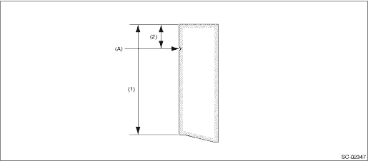
1. Measure the length of each brush. Replace the brush if wear exceeds service limits. There is a service limit mark (A) on each brush.
Brush length:
Standard (1)
22.5 mm (0.8858 in)
Service limit (2)
5.0 mm (0.1969 in)
2. Check that there is appropriate pressure on the brush spring. Using a spring pressure indicator, push the brush into the brush holder until its tip protrudes 2 mm (0.0787 in). Then measure the pressure of brush spring. If the pressure is 1.7 N (173 gf, 6.11 ozf) or less, replace the brush spring. 4.1 — 5.3 N (418 — 540 gf, 14.75 — 19.06 ozf) pressure is required on the new spring.
Check the ball bearings. Replace the ball bearings if there is resistance in the rotation, or if there is any abnormal noise.