1. Check the commutator for signs of seizure or stepped wear caused by roughness of the surface. If there is light wear, use sandpaper to repair.
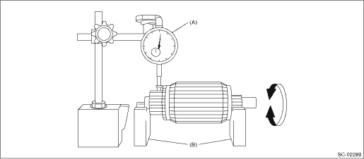
2. Run-out test
Check for run-out on the commutator. If excessive, replace it.
Commutator run-out:
Standard
0.05 mm (0.0020 in)
Service limit
0.10 mm (0.0039 in) or less
|
(A) |
Dial gauge |
(B) |
V-block |
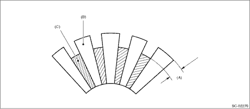
3. Depth of segment mold
Check the depth of the segment mold.
Depth of segment mold:
0.5 mm (0.0197 in)
|
(A) |
Depth of mold |
(B) |
Segment |
(C) |
Mold |
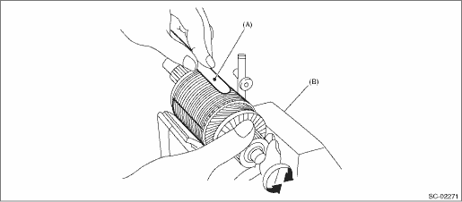
4. Armature short-circuit test
Place the armature on the growler tester to check for short circuits. While slowly turning the armature, support the steel sheet (thickness gauge, etc.) for the armature core. If the circuit of the armature is shorted, the steel sheet will vibrate, causing it to move towards the core. When the steel sheet has moved or vibrated, replace or repair the armature with the shorted circuit.
|
(A) |
Steel sheet (thickness gauge etc.) |
(B) |
Growler tester |
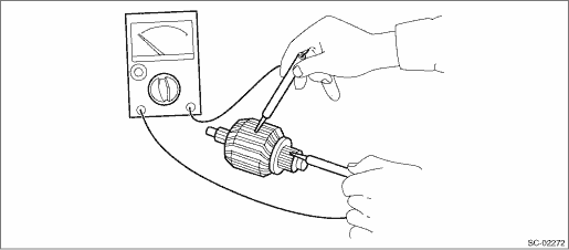
5. Armature ground test
Use a circuit tester to touch the probe of one side to the commutator segment, and the other probe to the shaft. If there is no continuity, it is normal. If there is continuity, the armature is grounded.
If grounded, replace the armature.
Make sure that the pole core is set at the predetermined position.
Check that there is no wear or damage to the piston teeth. Replace if damaged. If it rotates smoothly when rotated in the correct direction (counterclockwise) and does not return to the other direction, it is normal.
CAUTION:
To prevent spilling of grease, do not clean the overrunning clutch with oil.
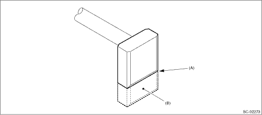
1. Brush length
Measure the length of the brush. If it exceeds service limits, replace it. Replace if there is abnormal wear or cracks.
Brush length:
Standard
12.3 mm (0.4843 in)
Service limit
7.0 mm (0.2756 in)
|
(A) |
Service limit line |
(B) |
Brush |
2. Brush movement
Check that the brush moves smoothly in the brush holder.
3. Brush spring force
Measure the brush spring force with a spring scale. Replace the brush holder assembly if below the service limit.
Brush spring force:
Standard
15.9 — 19.5 N (1.62 — 1.99 kgf, 3.57 — 4.38 lbf) (when new)
Service limit
2.5 N (0.25 kgf, 0.56 lbf)
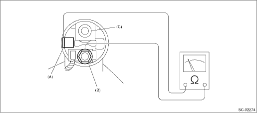
Using a circuit tester (set to “ohm”), check that there is continuity between terminals S and M, and between terminal S and ground. Also check to be sure there is no continuity between terminals M and B.
Terminal/Resistance:
S — M/1 Ω or less
S — Ground/1 Ω or less
M — B/1 MΩ or more
|
(A) |
S terminal |
(B) |
M terminal |
(C) |
B terminal |
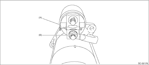
6. MAGNET SWITCH ASSEMBLY OPERATION
1. Using a lead wire, connect magnet switch assembly terminal S to the battery positive terminal, and the starter body to the battery ground terminal. The pinion should be forced endwise on shaft.
NOTE:
With the pinion forced endwise on shaft, starter motor can sometimes rotate because current flows, through pull-in coil, to motor. This is not a problem.
2. Disconnect the connector from M terminal. Then using a lead wire, connect the positive terminal of battery and M terminal and ground terminal to starter body. In this test set up, the pinion should return to its original position even when it is pulled out with a screwdriver.
|
(A) |
S terminal |
(B) |
M terminal |
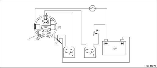
The starter should be placed through a no-load test whenever it has been overhauled, to assure its satisfactory performance when installed on the engine.
|
(A) |
Variable resistance |
(B) |
Magnet switch ASSY |
(C) |
Starter body |
1. No-load test
Adjust the variable resistance with the switch on until the voltage is 11 V, and read the value displayed by the ammeter to measure starter speed. Compare these values with the standard.
No-load test (standard):
Voltage/Current
Max. 11 V/130 A or less
Rotating speed
3,800 rpm or more