NOTE:
• Assemble in the reverse order of disassembly.
• Check and adjust each part during assembly.
• Use new gaskets and O-rings.
• Keep the shims and washers in order, so that they are not improperly installed.
• Thoroughly clean the surfaces on which the shims, washers and bearings are to be installed.
• Apply gear oil when installing the bearings.
• Be careful not to mix up the RH and LH bearing races.
• Replace the oil seals and O-rings with new parts at every disassembly.
• Apply differential gear oil to the lip when installing the oil seal.
• Be careful not to mix up the differential oil seal RH and LH.
1. Adjusting preload for front and rear bearings
NOTE:
Adjust the bearing preload between front and rear bearings with spacer and washer. Pinion height adjusting washer is not affected by this adjustment. The adjustment must not be carried out with oil seal inserted.
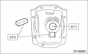
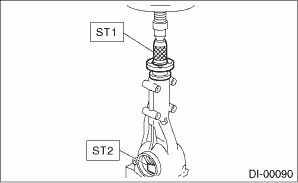
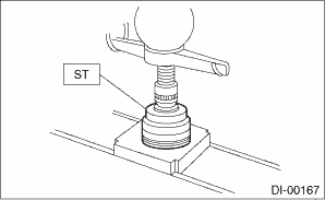
(1) Install the rear bearing race into the differential carrier using ST1 and ST2.
| ST1 398477701 | HANDLE |
| ST2 398477702 | DRIFT |
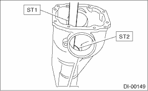
(2) Install the front bearing race to the differential carrier using ST1 and ST2.
| ST1 398477701 | HANDLE |
| ST2 498447110 | DRIFT |
(3) Insert the front bearing cone.
NOTE:
Use new front bearing cone.
(4) Measure and record the thickness of pinion height adjusting washer.
NOTE:
If tooth contact (drive pinion, hypoid driven gear) is normal in the inspection before disassembling, verify that the washer is not deformed, and then reuse the used washer.
(5) Insert ST1 into the case with the pinion height adjusting washer and rear bearing cone fitted onto it.
NOTE:
Use new rear bearing cone.
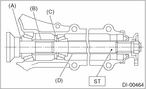
(6) Install the preload adjusting spacer and washer, front bearing cone, spacer, companion flange, and washer and self-locking nut.
| ST 498447150 | DUMMY SHAFT |
| Part No. 32285AA000 | SPACER |
|
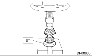
(A) |
Pinion height adjusting washer |
|
(B) |
Preload adjusting spacer |
|
(C) |
Preload adjusting washer |
|
(D) |
Spacer (SUBARU genuine parts) |
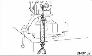
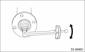
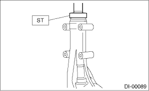
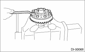
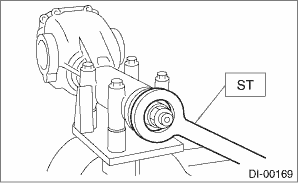
(7) Turn the ST1 by hand to smooth the bearing, and tighten the self-locking nut while measuring the initial load or initial torque with a spring scale or torque wrench. Select the preload adjusting washer and spacer so that the specified preload is obtained when nut is tightened to the specified torque.
NOTE:
• Use a new self-locking nut.
• Measure the preload in direction of tangent to the flange.
• Be careful not to give excessive preload.
• When tightening the self-locking nut, lock ST1 with ST2 as shown in the figure.
| ST1 498447150 | DUMMY SHAFT |
| ST2 398507704 | BLOCK |
Tightening torque:
191 N·m (19.5 kgf-m, 140.9 ft-lb)
Initial load:
12.7 — 32.2 N (1.3 — 3.3 kgf, 2.9 — 7.2 lbf)
Initial torque:
0.48 — 1.22 N·m (0.05 — 0.12 kgf-m, 0.35 — 0.90 ft-lb)
|
Preload adjusting washer | |
|
Part number |
Thickness mm (in) |
|
38336AA000 |
1.500 (0.0591) |
|
38336AA120 |
1.513 (0.0596) |
|
38336AA010 |
1.525 (0.0600) |
|
38336AA130 |
1.538 (0.0606) |
|
38336AA020 |
1.550 (0.0610) |
|
38336AA140 |
1.563 (0.0615) |
|
38336AA030 |
1.575 (0.0620) |
|
38336AA150 |
1.588 (0.0625) |
|
38336AA040 |
1.600 (0.0630) |
|
38336AA160 |
1.613 (0.0635) |
|
38336AA050 |
1.625 (0.0640) |
|
38336AA170 |
1.638 (0.0645) |
|
38336AA060 |
1.650 (0.0650) |
|
38336AA180 |
1.663 (0.0655) |
|
38336AA070 |
1.675 (0.0659) |
|
38336AA190 |
1.688 (0.0665) |
|
38336AA080 |
1.700 (0.0669) |
|
38336AA200 |
1.713 (0.0674) |
|
38336AA090 |
1.725 (0.0679) |
|
38336AA210 |
1.738 (0.0684) |
|
38336AA100 |
1.750 (0.0689) |
|
38336AA220 |
1.763 (0.0694) |
|
38336AA110 |
1.775 (0.0699) |
|
Preload adjusting spacer | |
|
Part number |
Length mm (in) |
|
32288AA040 |
52.3 (2.059) |
|
32288AA050 |
52.5 (2.067) |
|
31454AA100 |
52.6 (2.071) |
|
32288AA060 |
52.7 (2.075) |
|
31454AA110 |
52.8 (2.079) |
|
32288AA070 |
52.9 (2.083) |
|
31454AA120 |
53.0 (2.087) |
|
32288AA080 |
53.1 (2.091) |
|
32288AA090 |
53.3 (2.098) |
2. Adjusting drive pinion height:
Adjust the drive pinion height with washer installed between the rear bearing cone and the back of pinion gear.
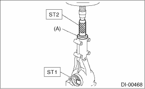
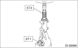
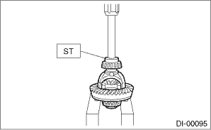
(1) Attach the ST2.
NOTE:
At this time, install a pinion height adjusting washer, temporarily selected, or the same as that used before.
| ST1 498447150 | DUMMY SHAFT |
| ST2 498505501 | DIFFERENTIAL CARRIER GAUGE |
| Part No. 32285AA000 | SPACER |
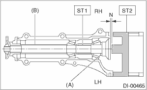
|
N |
Measured value |
|
(A) |
Pinion height adjusting washer |
|
(B) |
Spacer (SUBARU genuine parts) |
(2) Measure the clearance “N” between the end of ST2 and the end surface of ST1 by using a thickness gauge.
NOTE:
Make sure there is no clearance between the case and ST2.
| ST1 498447150 | DUMMY SHAFT |
| ST2 498505501 | DIFFERENTIAL CARRIER GAUGE |
(3) Obtain the thickness of pinion height adjusting washer to be inserted from the following formula, and replace the temporarily installed washer with this one.
NOTE:
Adjust it using the 1 — 3 washers.
T = To + N − 0.05 mm (0.002 in)
|
T |
Thickness of pinion height adjusting washer mm (in) |
|
|
To |
Thickness of washer temporarily inserted mm (in) |
|
|
N |
Clearance of thickness gauge mm (in) |
|
|
Memo: | ||
(Example of calculation)
To = 0.15 mm (0.0059 in)
N = 0.1 mm (0.0039 in)
T = 0.15 + 0.1 − 0.05 = 0.2 mm (0.0079 in)
Thickness = 0.2 mm (0.0079 in)
Therefore use part number 32295AA220.
|
Pinion height adjusting washer | |
|
Part number |
Thickness mm (in) |
|
32295AA200 |
0.150 (0.0059) |
|
32295AA210 |
0.175 (0.0069) |
|
32295AA220 |
0.200 (0.0079) |
|
32295AA230 |
0.225 (0.0089) |
|
32295AA240 |
0.250 (0.0098) |
|
32295AA250 |
0.275 (0.0108) |
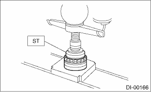
3. Install the selected pinion height adjusting washer on drive pinion, and press the rear bearing cone into position with ST.
| ST 498175500 | INSTALLER |
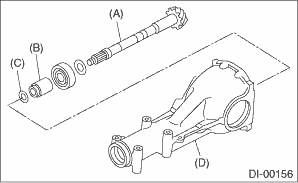
4. Insert the drive pinion into the differential carrier, and install the preselected bearing preload adjusting spacer and washer.
|
(A) |
Drive pinion |
|
(B) |
Bearing preload adjusting spacer |
|
(C) |
Bearing preload adjusting washer |
|
(D) |
Differential carrier |
5. Press-fit the front bearing cone into the carrier with ST1, ST2 and the spacer.
| ST1 399780104 | WEIGHT |
| ST2 899580100 | INSTALLER |
| Part No. 32285AA000 | SPACER |
|
(A) |
Spacer (SUBARU genuine parts) |
6. Insert the spacer, then press-fit the pilot bearing with ST1 and ST2.
| ST1 399780104 | WEIGHT |
| ST2 899580100 | INSTALLER |
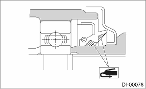
7. Fit a new oil seal with ST.
NOTE:
• Press-fit until the oil seal end comes 1 mm (0.04 in) inward from end of carrier.
• Apply differential gear oil to the oil seal lips.
| ST 498447120 | INSTALLER |
8. Press-fit the companion flange with ST1 and ST2.
NOTE:
Be careful not to damage the bearing.
| ST1 899874100 | INSTALLER |
| ST2 399780104 | WEIGHT |
9. Attach the new self-locking nut and use the ST to fix the companion flange in place, then tighten the nut.
NOTE:
Before installing self-locking nut, apply a sealing material to self-locking nut threads.
SEAL MATERIAL:
THREE BOND 1324 (Part No. 004403042) or equivalent
| ST 498427200 | FLANGE WRENCH |
Tightening torque:
191 N·m (19.5 kgf-m, 140.9 ft-lb)
10. Check the initial torque and initial load.
Initial load:
12.7 — 32.2 N (1.3 — 3.3 kgf, 2.9 — 7.2 lb)
Initial torque:
0.48 — 1.22 N·m (0.05 — 0.12 kgf-m, 0.35 — 0.90 ft-lb)
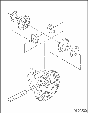
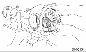
11. Assembling differential case
Install the side gears and pinion mate gears, with the thrust washers and pinion mate shaft, into the differential case.
NOTE:
• Apply gear oil on both sides of the washer and on the side gear shaft before installing.
• Insert the pinion mate shaft into the differential case by aligning the lock pin holes.
(1) Measure the side gear backlash.
Side gear backlash:
0.05 — 0.15 mm (0.002 — 0.006 in)
(2) Adjust the side gear backlash as specified by selecting side gear thrust washer.
|
Side gear thrust washer | |
|
Part number |
Thickness mm (in) |
|
803135011 |
0.925 — 0.950 (0.0364 — 0.0374) |
|
803135012 |
0.950 — 0.975 (0.0374 — 0.0384) |
|
803135013 |
0.975 — 1.000 (0.0384 — 0.0394) |
|
803135014 |
1.000 — 1.025 (0.0394 — 0.0404) |
|
803135015 |
1.025 — 1.050 (0.0404 — 0.0413) |
(3) Check the condition of rotation after applying oil to the gear tooth surfaces and thrust surfaces.
(4) After inserting the pinion shaft lock pin into differential case, stake the both sides of the hole to prevent pin from falling off.
12. Install the hypoid driven gear to differential case.
NOTE:
• Before installing bolts, apply a sealing material to bolt threads.
SEAL MATERIAL:
THREE BOND 1324 (Part No. 004403042) or equivalent
• Tighten diagonally.
Tightening torque:
62 N·m (6.3 kgf-m, 45.7 ft-lb)
13. Press the side bearing into the differential case using ST.
| ST 498485400 | DRIFT |
14. Assemble the side retainer.
(1) Install the oil seal into side retainer RH and LH.
| ST 498447100 | INSTALLER |
(2) Install the bearing race into side retainer RH and LH.
| ST 398477702 | DRIFT |
CAUTION:
Make sure that the RH and LH oil seals, bearing outer races and cones are properly assembled.
(3) Install the differential case assembly into differential carrier in the reverse order of disassembly.
NOTE:
Be careful not to hit the teeth against the case.
(4) Slightly screw in the side retainer RH and LH to the differential carrier to install.
15. Perform the backlash adjustment between the hypoid driven gear and drive pinion, and preload adjustment of differential side bearing.
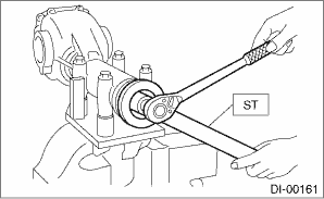
(1) Turn the drive pinion with ST for better fitting of differential side bearing.
| ST 498427200 | FLANGE WRENCH |
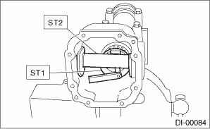
(2) Using the ST, tighten side retainer RH, and then tighten side retainer LH until there is no backlash.
| ST 18630AA010 | WRENCH COMPL RETAINER |

(3) Back off the side retainer LH by approx. 1.5 teeth, and tighten the side retainer RH by approx. 2 teeth (amount that the side retainer LH is turned back (1.5) + 1/2 teeth).
Difference between [amount that the side retainer LH is turned back (approx. 1 and 1/2 teeth)] and [amount that the side retainer RH is tightened (approx. 2 teeth)] gives preload.
(4) Temporarily tighten the lock plate.
NOTE:
Turn over the lock plate to shift the holder by 1/2 tooth.
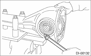
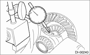
(5) Measure the hypoid driven gear-to-drive pinion backlash. Set the magnet base on differential carrier. Align the contact point of dial gauge with tooth face of hypoid driven gear, and move hypoid driven gear while holding drive pinion still. Read the value indicated on dial gauge.
NOTE:
If measured value of backlash is not within the specified range, repeat the procedures for pinion driven gear set backlash adjustment and the differential side bearing preload adjustment.
Backlash:
0.10 — 0.15 mm (0.004 — 0.006 in)
16. Put alignment marks on both the differential carrier and side retainer. Remove the side retainer side at a time.
Replace them in the original position after inserting an O-ring and applying gear oil to the threaded portion.
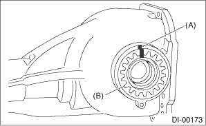
|
(A) |
Alignment mark |
|
(B) |
Side retainer |
17. Tighten the bolt of lock plate to specified torque.
Tightening torque:
25 N·m (2.5 kgf-m, 18.4 ft-lb)
18. Recheck the hypoid driven gear to pinion backlash.
Backlash:
0.10 — 0.15 mm (0.004 — 0.006 in)
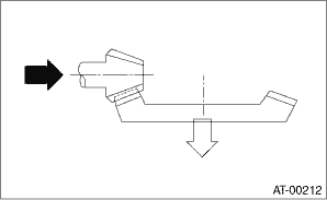
19. Checking and adjusting the tooth contact of hypoid driven gear
(1) Apply lead-free red dye evenly on the both sides of three to four teeth of the hypoid driven gear. Check the contact pattern after rotating the hypoid driven gear several revolutions back and forth until a definite contact pattern appears on the hypoid driven gear.
(2) When the contact pattern is not correct, readjust.
NOTE:
Be sure to wipe off the lead-free red dye completely after the adjustment is completed.
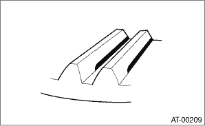
• Correct tooth contact
Check item: Tooth contact pattern is slightly shifted toward toe side under no-load rotation. (When driving, it moves towards the heel side.)
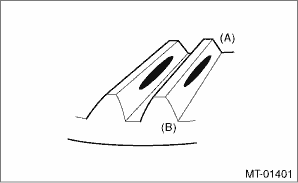
|
(A) |
Toe side |
|
(B) |
Heel side |
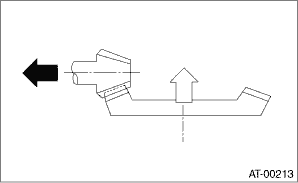
• Face contact
Check item: Backlash is too large.
Contact pattern
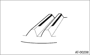
Corrective action: Increase thickness of pinion height adjusting washer according to the procedure for bringing drive pinion close to hypoid driven gear side.
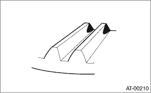
• Flank contact
Check item: Backlash is too small.
Contact pattern
Corrective action: Reduce the thickness of pinion height adjusting washer according to the procedure for bringing drive pinion away from hypoid driven gear.
• Toe contact (inside contact)
Check item: Teeth contact area is too small.
Contact pattern
Corrective action: Reduce the thickness of pinion height adjusting washer according to the procedure for bringing drive pinion away from hypoid driven gear side.
• Heel contact (outside end contact)
Check item: Teeth contact area is too small.
Contact pattern
Corrective action: Increase thickness of pinion height adjusting washer according to the procedure for bringing drive pinion close to hypoid driven gear side.
20. If correct tooth contact is not obtained, once again adjust the drive pinion height, the differential side bearing preload (already mentioned) and the hypoid gear backlash.
21. Install the new gasket and rear cover to the differential carrier, and tighten the bolts to specified torque.
Tightening torque:
25 N·m (2.5 kgf-m, 18.4 ft-lb)
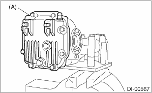
|
(A) |
Rear cover |
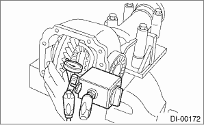
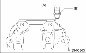
22. Install the air breather cap.
NOTE:
When installing the air breather cap, do not tap section (A). Be sure to tap section (B) to install.
23. Install the oil drain plug and filler plug.
Tightening torque:
34 N·m (3.5 kgf-m, 25.1 ft-lb)