CAUTION:
• Do not remove unless replacing.
• If the sensor needs replacement, replace along with the combination switch assembly once every three times for the protection of the threaded portion.
1. Set the steering wheel in a straight-ahead position.
2. Disconnect the ground cable from battery.
3. Remove the airbag module.

WARNING:
Always refer to “Airbag System” when performing the airbag module repair service.
4. Remove the steering wheel.
5. Remove the screws, and remove the steering column lower cover.
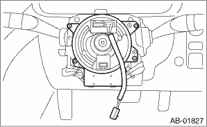
6. Remove the two screws securing the steering column upper cover.
7. Disconnect the connectors of roll connector and steering angle sensor.
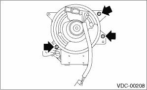
8. Remove the screws which secure the roll connector to steering column.
9. Remove the vinyl tape binding the harness, and remove the steering angle sensor from roll connector.
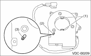
10. Turn the protrusion portion of new steering angle sensor to match the alignment mark of inspection hole.
|
(1) |
Protrusion portion |
|
(2) |
Inspection hole |
|
(3) |
Alignment mark |
CAUTION:
Be careful not to allow foreign matter to enter into inspection hole.
11. Align the center of roll connector.
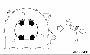
12. Apply the grease provided with the new part on the four locations of the protrusion on the steering angle sensor.
|
(1) |
Grease application location |
13. Align the position of the protrusion and install roll connector to steering angle sensor.
Tightening torque:
0.5 N·m (0.05 kgf-m, 0.36 ft-lb)
14. Install the roll connector to combination switch and bind the harness with vinyl tape as originally bound.
15. Install the steering wheel.
Tightening torque:
39 N·m (4.0 kgf-m, 28.8 ft-lb)
16. Install the airbag module to the steering wheel.
WARNING:
Always refer to “Airbag System” before performing the service operation.
17. Connect the ground cable to the battery.
CAUTION:
After completion of installation, adjust the following two positions.
• Positioning to the center of steering angle sensor
• Positioning the yaw rate & lateral G sensor to zero.
The above procedure is required for the VDCCM to identify vehicle position afterward. For the setting procedures of the two steps above, refer to “VDC Control Module and Hydraulic Control Unit (VDCCM&H/U)”.