CAUTION:
• Because the pressure sensor built into the H/U is easily damaged by static electricity, start the operation after performing static electricity measures.
• Be careful not to touch the sensors in the H/U to prevent damage.
• Because the seal of the VDCCM cannot be replaced, do not pull or peel it by lifting it up.
• Because the screw of the H/U will become slightly worn in every replacement procedure, 5 times is the maximum number of times for replacement. If a problem is found such as not being able to torque the screw to specifications even before 5 replacement operations are performed, replace the H/U body.
• When installing the VDCCM, always use new screws.
• When the sealing surface of the VDCCM or H/U is dirty or damaged and it cannot be cleaned or repaired, replace with a new part.
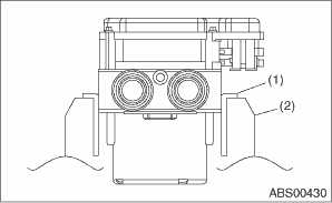
1. Remove the VDCCM&H/U. 
2. To prevent entry of foreign objects and brake fluid leakage, plug the oil pressure port of the VDCCM&H/U using a screw plug, etc.
3. Set the pump motor section of the removed VDCCM&H/U face down on a vise.
NOTE:
Before securing a part in a vise, place cushioning material such as wood blocks, aluminum plate or cloth between the part and the vise.
|
(1) |
Aluminum plate, etc. |
|
(2) |
Vise |
4. Using TORX® bit E5, remove the four screws of VDCCM.
NOTE:
These screws cannot be reused.
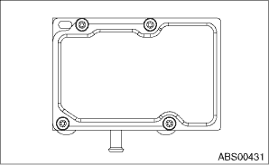
5. Slowly pull out the VDCCM upward from the H/U.
NOTE:
To prevent damaging of coil section, remove the VDCCM straight up from H/U without twisting.
6. Make sure there is no dirt or damage on the sealing surface of the H/U.
CAUTION:
• Do not clean the VDCCM&H/U by applying compressed air.
• Even if damage is found on the H/U seal, do not attempt repair by filing or with a metal scraper. To remove the seal residue, always use a plastic scraper. Do not use chemical such as paint thinner, etc., to clean.
7. Position the coil of the new VDCCM to align with the H/U valve.
8. To prevent deformation of the VDCCM housing cover, hold the corner of VDCCM and install it to the H/U without tilting.
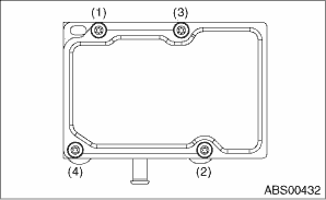
9. Using a TORX® bit E5, attach/tighten new screws in the order of (1) through (4).
CAUTION:
Always use new screws.
Tightening torque:
1.5 N·m (0.15 kgf-m, 1.1 ft-lb)
10. Check that there is no foreign matter in mating surface between the VDCCM&H/U.
11. Using a TORX® bit E5, tighten the screws in the order of (1) through (4) again.
Tightening torque:
3 N·m (0.3 kgf-m, 2.2 ft-lb)
12. Check that there is no gap in the mating surface between VDCCM&H/U.
13. Install the VDCCM&H/U to the vehicle.
14. Bleed air from the brake system.
15. Perform the selection and registration operation of parameter.
NOTE:
• After replacing the VDCCM, be sure to perform the selection and registration operation of parameter.
• For the selection and registration of parameter, the Subaru Select Monitor is required.
• When no data is registered, ABS/EBD/VDC warning light illuminates and the DTC “Parameter selection error” is detected.
16. Check the parameters to confirm that the applied models and grades of the relevant vehicle are included.
17. If the applied model and grade of the relevant vehicle are not included on the {Confirm on parameter} display screen, perform parameter selection and registration again.
18. Execute Clear Memory after parameter selection and registration operations because the DTC for “Parameter selection error” is memorized.