Install in the reverse order of removal.
NOTE:
• Refer to “COMPONENT” for each tightening torque. 
• When installing the plate guide COMPL, set the select lever to “D” range (normal mode position), and be careful of the following.
• Insert protrusion (B) of the plate guide COMPL into the hole on the shift lock solenoid unit (A).
• Insert the shift lock release link (D) into the shift lock solenoid unit link (C).
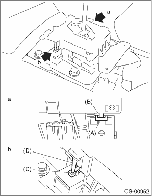
• Connect the switch and solenoid terminals to the connector.
|
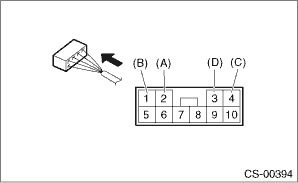
(A) |
“P” range switch (color code: white) |
|
(B) |
“P” range switch (color code: black) |
|
(C) |
Shift lock solenoid (color code: blue/red) |
|
(D) |
Shift lock solenoid (color code: black) |