NOTE:
• Assembly is available only for 5MT model.
• Clean all the parts before assembly.
• Apply NIGTIGHT LYW No. 2 grease or equivalent to each part. 
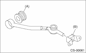
1. Mount the bushing and cushion rubber to the stay.
|
(A) |
Bushing |
|
(B) |
Cushion rubber |
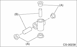
2. Install the bushing and spacer to boss.
|
(A) |
Bushing |
|
(B) |
Spacer |
3. Using new self-locking nuts, install the boss to the joint.
Tightening torque:
12 N·m (1.2 kgf-m, 8.9 ft-lb)
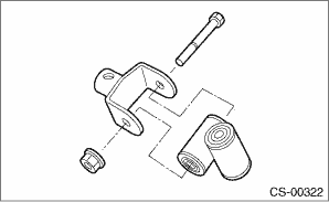
4. Install the snap ring to gear shift lever and install the bushing.
NOTE:
Apply grease to the bushing.
|
(A) |
Spring pin |
|
(B) |
Bushing |
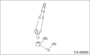
5. Apply grease to the bushing and O-ring, and then install to gear shift lever.
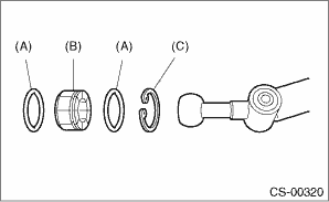
|
(A) |
O-ring |
|
(B) |
Bushing |
|
(C) |
Snap ring |
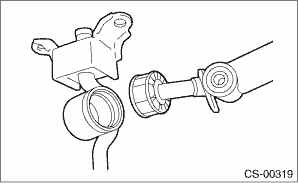
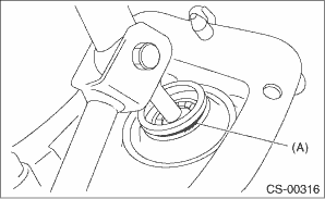
6. Apply sufficient grease into boss, and then install the gear shift lever to the stay.
7. Install the washer and snap ring.
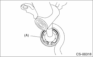
|
(A) |
Snap ring |
8. Insert the gear shift lever and rod into boot hole.
9. Install the rod.
Tightening torque:
12 N·m (1.2 kgf-m, 8.9 ft-lb)
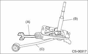
|
(A) |
Rod |
|
(B) |
Lever |
|
(C) |
Stay |
10. Install a new lock wire.
|
(A) |
Lock wire |
NOTE:
• Install the lock wire to the stay groove.
• Bend the extra wire to the same direction of lock wire winding.
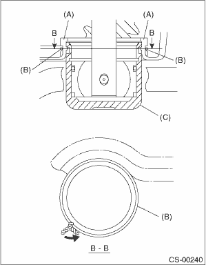
|
(A) |
Inner boot |
|
(B) |
Lock wire |
|
(C) |
Stay |