1. Clean all the parts before assembly.
2. Apply NIGTIGHT LYW No. 2 grease or equivalent to each part. 
3. Assemble in the reverse order of disassembly.
NOTE:
• When installing the plate guide COMPL, set the select lever to “D” range (normal mode position), and be careful of the following.
• Insert protrusion (B) of the plate guide COMPL into the hole on the shift lock solenoid unit (A).
• Insert the shift lock release link (D) into the shift lock solenoid unit link (C).
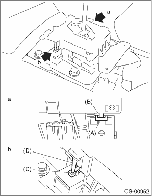
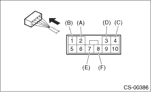
• Connect the switch and solenoid terminals to the connector.
|
(A) |
“P” range switch (color code: white) |
|
(B) |
“P” range switch (color code: black) |
|
(C) |
Shift lock solenoid (color code: blue/red) |
|
(D) |
Shift lock solenoid (color code: black) |
|
(E) |
SPORT mode switch (color code: white) |
|
(F) |
SPORT mode switch (color code: black) |
4. After completing installation, shift the select lever from “P” range to “D” range, then check whether the indicator and select lever matches, whether the pointer and position mark matches and what the operating force is.