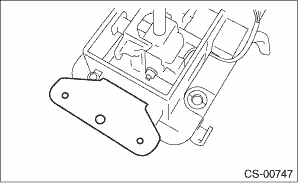
1. Remove the gasket and plate COMPL.
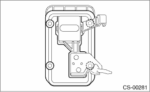
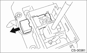
2. Insert a flat tip screwdriver with a thin tip under the connector and disconnect each connector from the plate COMPL.
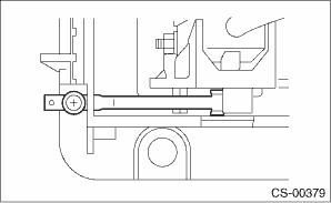
3. Remove the spacer bolt and remove the plate guide COMPL.
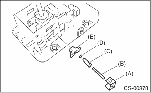
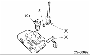
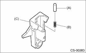
4. Remove the shift lock clamp, spring A, select lever rod, lock plate cushion, and bushing.
|
(A) |
Shift lock clamp |
|
(B) |
Spring A |
|
(C) |
Select lever rod |
|
(D) |
Lock plate cushion |
|
(E) |
Bushing |
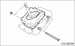
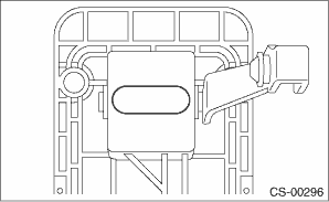
5. Remove the bracket.
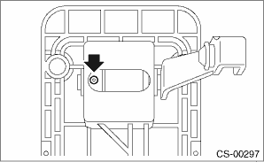
6. Remove the detent spring.
7. Remove shift lock solenoid unit.
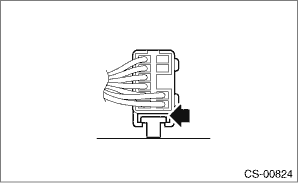
8. Raise the claw of connector.
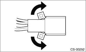
9. Using a thin flat tip screwdriver, remove the terminals of the SPORT mode switch, “P” range switch and shift lock solenoid unit from the connector.
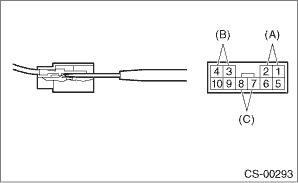
|
(A) |
“P” range switch terminal |
|
(B) |
Shift lock solenoid terminal |
|
(C) |
SPORT mode switch terminal |
10. Remove the grommet.
11. Pull out the spring pin.
12. Pull out the arm COMPL, remove the select lever COMPL, and remove the bracket arm detent and bushing.
|
(A) |
Arm COMPL |
|
(B) |
Selector lever COMPL |
|
(C) |
Bracket arm detent |
|
(D) |
Bushing |
13. Remove the rod detent and spring detent from the bracket arm detent.
|
(A) |
Rod detent |
|
(B) |
Spring detent |
|
(C) |
Bracket arm detent |