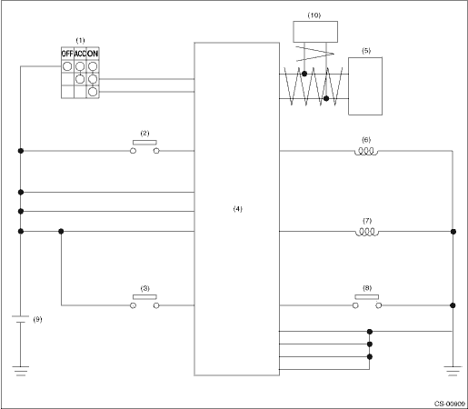
1. MODEL WITHOUT PUSH BUTTON IGNITION SWITCH

|
(1) |
Ignition switch |
(5) |
TCM (shift range information) |
(9) |
Battery |
|
(2) |
Stop light switch |
(6) |
Key lock solenoid |
(10) |
VDC (vehicle speed information) |
|
(3) |
Key warning switch |
(7) |
Shift lock solenoid |
||
|
(4) |
Body integrated unit |
(8) |
“P” range switch |
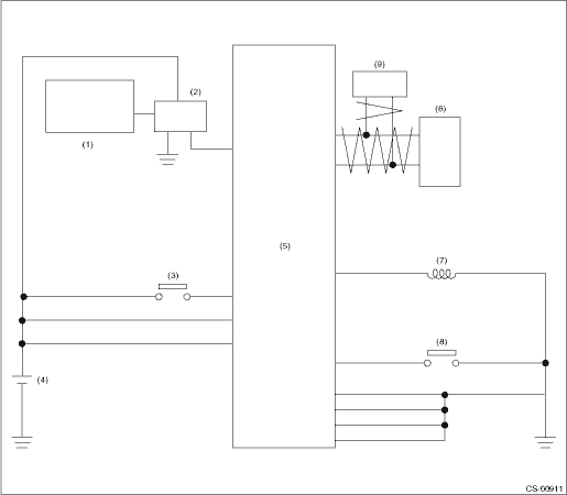
2. MODEL WITH PUSH BUTTON IGNITION SWITCH
|
(1) |
Power supply CM |
(4) |
Battery |
(7) |
Shift lock solenoid |
|
(2) |
IG relay 2 (push button start) |
(5) |
Body integrated unit |
(8) |
“P” range switch |
|
(3) |
Stop light switch |
(6) |
TCM (shift range information) |
(9) |
VDC (vehicle speed information) |