1. ATF COOLER (WITHOUT WARMER FEATURE) MODELS
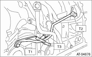
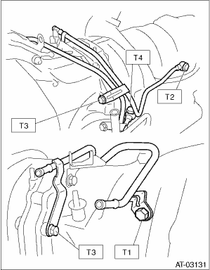
1. Install the ATF inlet pipe and outlet pipe along with new washers.
Tightening torque:
T1: 25 N·m (2.5 kgf-m, 18.4 ft-lb)
T2: 40 N·m (4.1 kgf-m, 29.5 ft-lb)
T3: 45 N·m (4.6 kgf-m, 33.2 ft-lb)
2. Install the ATF cooler pipe to frame.
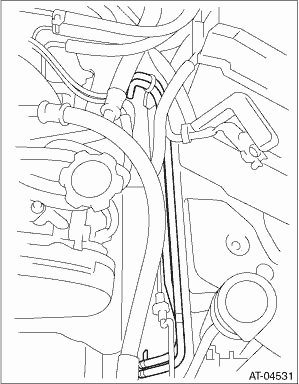
3. Connect the ATF cooler hose to the pipe on the transmission side.
NOTE:
• Install so that the hose is not folded over, excessively bent or twisted.
• Insert the hose to the specified position.
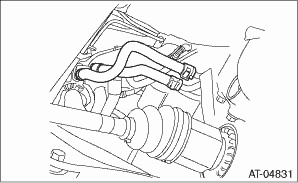
4. Connect the ATF cooler hose to the pipe on the radiator side.
NOTE:
• Install so that the hose is not folded over, excessively bent or twisted.
• Insert the hose to the specified position.
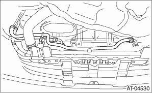
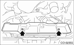
5. Install the heat shield cover.
Tightening torque:
3 N·m (0.3 kgf-m, 2.2 ft-lb)
6. Install the under cover.
7. Install the battery.
8. Fill ATF. 
NOTE:
Make sure there are no ATF leaks in joints between the transmission, radiator, pipes, and hoses.
2. ATF COOLER (WITH WARMER FEATURE) MODELS
1. Install the ATF inlet and outlet pipes with the new washers.
NOTE:
Use a new bolt for the position tightened together with the mounting bolt for converter case and transmission case.
Tightening torque:
T1: 21 N·m (2.1 kgf-m, 15.5 ft-lb)
T2: 40 N·m (4.1 kgf-m, 29.5 ft-lb)
T3: 38 N·m (3.9 kgf-m, 28.0 ft-lb)
T4: 45 N·m (4.6 kgf-m, 33.2 ft-lb)
2. Install the ATF cooler assembly to the transmission.
Tightening torque:
23 N·m (2.3 kgf-m, 17.0 ft-lb)
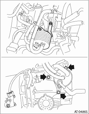
3. Install the oil charge pipe.
4. Install the inlet and outlet hoses.
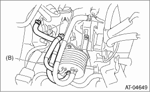
|
(A) |
Inlet hose |
|
(B) |
Outlet hose |
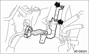
5. Install the engine harness bracket.
Tightening torque:
16 N·m (1.6 kgf-m, 11.8 ft-lb)
6. Install the inhibitor switch connector and transmission harness connectors to the stay, then connect the harness connector.
7. Install the air breather hose.
8. Install the air intake chamber and intake boot.
9. Check the ATF level.