1. HIGH CLUTCH AND REVERSE CLUTCH
1. Install a new seal ring and lip seal to the high clutch piston and reverse clutch piston.
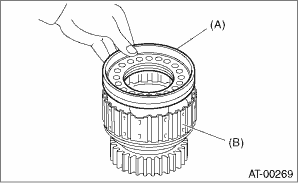
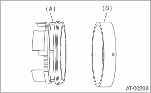
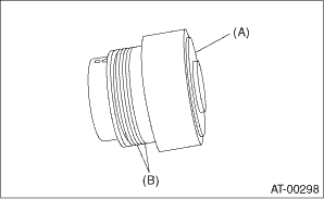
2. Install the high clutch piston to the reverse clutch piston.
NOTE:
Be careful not to damage the seal ring and lip seal.
|
(A) |
High clutch piston |
|
(B) |
Reverse clutch piston |
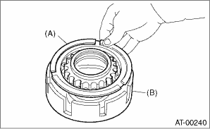
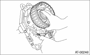
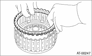
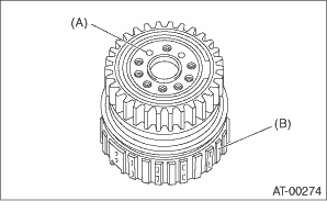
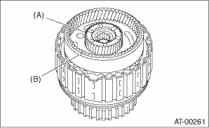
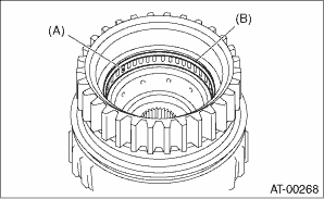
3. Install the reverse clutch piston to the high clutch drum. Align the groove on reverse clutch piston with the groove on high clutch drum during installation.
|
(A) |
Reverse clutch piston |
|
(B) |
High clutch drum |
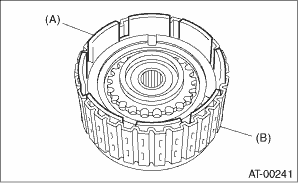
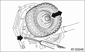
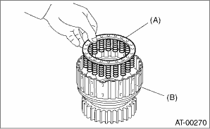
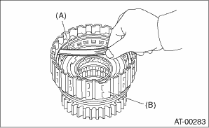
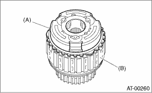
4. Install the spring retainer to the high clutch piston.
|
(A) |
Spring retainer |
|
(B) |
High clutch drum |
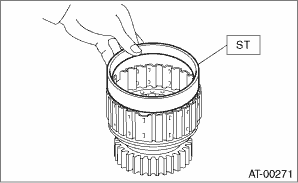
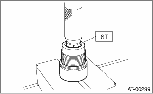
5. Attach the ST to the high clutch piston.
| ST 498437000 | HIGH CLUTCH PISTON GUIDE |
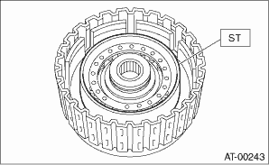
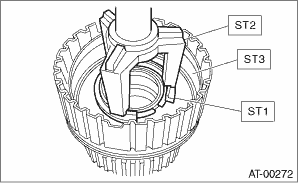
6. Install the high clutch piston cover while making sure not to break the high clutch piston seal.
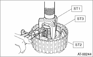
7. Using the ST1, ST2 and ST3, install the snap ring.
| ST1 398673600 | COMPRESSOR |
| ST2 498627100 | SEAT |
| ST3 498437000 | HIGH CLUTCH PISTON GUIDE |
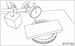
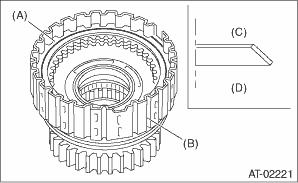
8. Measure and record a amount of drive plate compression. (non-turbo model)
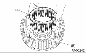
(1) Place the dish plate, driven plate, drive plate and retaining plate neatly in this order on surface table.
(2) Set the micro gauge to clutch, and read its scale.
NOTE:
The value, which is read in the gauge at this time, is zero point.
(3) Scale and record the weight “Z” of a flat board which will be put on retaining plate.
NOTE:
• Use a stiff board which does not bend against load as a flat board to be put on retaining plate.
• Use a flat board weighing less than 25.5 kg (56.2 lb).
(4) Put the flat board on retaining plate.
(5) Using the following formula, read the push/pull gauge, and calculate “N”.
N = 250 N (25.5 kgf, 56.2 lb) − Z
N: Value indicated on push/pull gauge
250 N (25.5 kgf, 56.2 lb) : Load applied to clutch plate
Z: Flat board weight
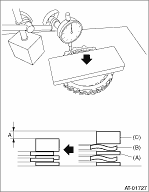
(6) Press the center of retaining plate by applying a force of N using push/pull gauge, and then measure and record the height “A”. Measure at three or more locations spaced by equal distances and take the average value.
NOTE:
If measuring in three locations, measure every 120°. If measuring in four locations, measure every 90°.
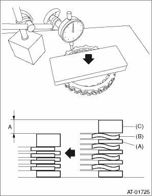
|
(A) |
Driven plate |
|
(B) |
Drive plate |
|
(C) |
Retaining plate |
9. Install the thickest driven plate to piston side, and then install the driven plate, drive plate, retaining plate to high clutch drum.
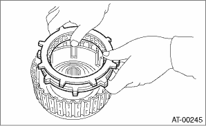
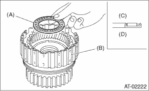
10. Install the snap ring to high clutch drum.
11. Apply compressed air intermittently to check for operation.
12. Check the piston stroke. (non-turbo model)
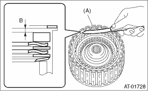
(1) Measure clearance “B” between the retaining plate and snap ring. (High clutch)
At this time, do not press down the retaining plate.
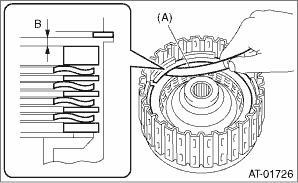
|
(A) |
Thickness gauge |
(2) Piston stroke calculation
Calculate with A and B dimensions recorded before. If the calculated value exceeds the service limits, replace the drive plate and select and adjust the retaining plate to be within initial standard values.
T = A + B
T: Piston stroke
A: Amount of drive plate compression
B: Clearance between retaining plate and snap ring
Initial standard:
2.0 — 2.3 mm (0.079 — 0.091 in)
Limit thickness:
2.6 mm (0.102 in)
|
Retaining plate | |
|
Part No. |
Thickness mm (in) |
|
31567AA710 |
4.7 (0.185) |
|
31567AA720 |
4.8 (0.189) |
|
31567AA730 |
4.9 (0.193) |
|
31567AA740 |
5.0 (0.197) |
|
31567AA670 |
5.1 (0.201) |
|
31567AA680 |
5.2 (0.205) |
|
31567AA690 |
5.3 (0.209) |
|
31567AA700 |
5.4 (0.213) |
13. Measure the clearance between the high clutch retaining plate and snap ring. (turbo model)
At this time, do not press down the retaining plate.
Initial standard:
0.8 — 1.1 mm (0.031 — 0.043 in)
Limit thickness:
1.5 mm (0.059 in)
|
(A) |
Thickness gauge |
If the clearance exceeds the service limits, replace the drive plate and select and adjust the retaining plate to make the clearance fall within initial standard values.
|
High clutch retaining plate | |
|
Part No. |
Thickness mm (in) |
|
31567AA710 |
4.7 (0.185) |
|
31567AA720 |
4.8 (0.189) |
|
31567AA730 |
4.9 (0.193) |
|
31567AA740 |
5.0 (0.197) |
|
31567AA670 |
5.1 (0.201) |
|
31567AA680 |
5.2 (0.205) |
|
31567AA690 |
5.3 (0.209) |
|
31567AA700 |
5.4 (0.213) |
14. Selection of the reverse clutch retaining plate
(1) Place the dish plate, driven plate, drive plate and retaining plate neatly in this order on surface table.
(2) Set the micro gauge to retaining plate, and read its scale.
NOTE:
The value, which is read in the gauge at this time, is zero point.
(3) Scale and record the weight “Z” of a flat board which will be put on retaining plate.
NOTE:
• Use a stiff board which does not bend against load as a flat board to be put on retaining plate.
• Use a flat board weighing less than 15.3 kg (33.7 lb).
(4) Put the flat board on retaining plate.
(5) Using the following formula, read the push/pull gauge, and calculate “N”.
N = 150 N (15.3 kgf, 33.7 lbf) − Z
N: Value indicated on push/pull gauge
150 N (15.3 kgf, 33.7 lbf): Load applied to the clutch plate
Z: Flat board weight
(6) Press the center of retaining plate by applying a force of N using push/pull gauge, and then measure and record the height “A”. Measure at three or more locations spaced by equal distances and take the average value.
NOTE:
If measuring in three locations, measure every 120°. If measuring in four locations, measure every 90°.
|
(A) |
Driven plate |
|
(B) |
Drive plate |
|
(C) |
Retaining plate |
(7) Install the driven plate, drive plate, retaining plate and snap ring.
(8) Apply compressed air intermittently to check for operation.
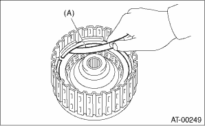
(9) Measure clearance “B” between the retaining plate and snap ring. (Reverse clutch)
At this time, do not press down the retaining plate.
|
(A) |
Thickness gauge |
(10) Piston stroke calculation
Calculate with A and B dimensions recorded before. If the calculated value exceeds the service limits, replace the drive plate and select and adjust the retaining plate to be within initial standard values.
T = A + B
T: Piston stroke
A: Amount of drive plate compression
B: Clearance between retaining plate and snap ring
Initial standard:
1.1 — 1.4 mm (0.043 — 0.055 in)
Limit thickness:
1.6 mm (0.063 in)
|
Retaining plate | |
|
Part No. |
Thickness mm (in) |
|
31567AA910 |
4.0 (0.157) |
|
31567AA920 |
4.2 (0.165) |
|
31567AA930 |
4.4 (0.173) |
|
31567AA940 |
4.6 (0.181) |
|
31567AA950 |
4.8 (0.189) |
|
31567AA960 |
5.0 (0.197) |
|
31567AA970 |
5.2 (0.205) |
|
31567AA980 |
5.4 (0.213) |
2. PLANETARY GEAR AND LOW CLUTCH
1. Apply ATF to a new D-ring, and install it to the low clutch piston.
2. Install the low clutch piston to low clutch drum.
NOTE:
Be careful not to damage the D-ring.
|
(A) |
Low clutch piston |
|
(B) |
Low clutch drum |
3. Install the spring retainer to low clutch piston.
|
(A) |
Spring retainer |
|
(B) |
Low clutch drum |
4. Attach the ST to the low clutch drum.
| ST 498437100 | LOW CLUTCH PISTON GUIDE |
5. Using ST1, ST2, and ST3, set the cover on the piston and press against it, and attach the snap ring. At this time, be careful not to bend the cover seal.
| ST1 498627100 | SEAT |
| ST2 398673600 | COMPRESSOR |
| ST3 498437100 | LOW CLUTCH PISTON GUIDE |
6. Install the dish plate, driven plate, drive plate and retaining plate, and then secure them with a snap ring.
|
(A) |
Snap ring |
|
(B) |
Low clutch drum |
|
(C) |
Dish plate |
|
(D) |
Low clutch piston side |
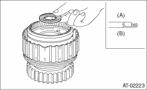
7. Check the low clutch for operation.
(1) Remove the one-way clutch. 
(2) Set the one-way clutch inner race, and apply compressed air for checking.
|
(A) |
Apply compressed air. |
|
(B) |
Low clutch drum |
8. Check the low clutch clearance.
(1) Place same thickness shims on both sides to prevent plate from tilting.
(2) Check the clearance between retaining plate and low clutch operation.
Initial standard:
0.7 — 1.1 mm (0.028 — 0.043 in)
Limit thickness:
1.6 mm (0.063 in)
|
(A) |
Thickness gauge |
|
(B) |
Low clutch drum |
If the clearance exceeds the service limits, replace the drive plate and select and adjust the retaining plate to make the clearance fall within initial standard values.
|
Retaining plate | |
|
Part No. |
Thickness mm (in) |
|
31567AB050 |
3.8 (0.150) |
|
31567AB060 |
4.0 (0.157) |
|
31567AB070 |
4.2 (0.165) |
|
31567AB080 |
4.4 (0.173) |
|
31567AB090 |
4.6 (0.181) |
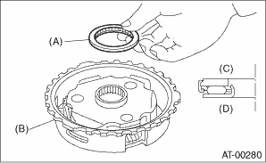
9. Install the washer to the rear internal gear.
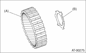
|
(A) |
Rear internal gear |
|
(B) |
Washer |
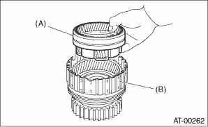
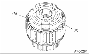
10. Install the rear internal gear.
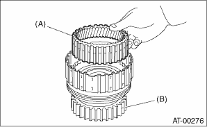
|
(A) |
Rear internal gear |
|
(B) |
Low clutch drum |
11. Install the thrust needle bearing in the correct direction.
|
(A) |
Thrust needle bearing |
|
(B) |
Low clutch drum |
|
(C) |
Rear planetary, carrier side |
|
(D) |
Low clutch drum side |
12. Install the washer by aligning the protrusion of the washer with the hole of the rear planetary carrier.
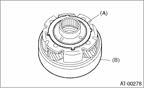
|
(A) |
Washer |
|
(B) |
Rear planetary carrier |
13. Install the rear planetary carrier to the low clutch drum.
|
(A) |
Rear planetary carrier |
|
(B) |
Low clutch drum |
14. Install the thrust needle bearing in the correct direction.
|
(A) |
Rear sun gear side |
|
(B) |
Low clutch drum side |
15. Install the rear sun gear in the correct direction.
|
(A) |
Rear sun gear |
|
(B) |
Rear planetary carrier |
16. Install the thrust needle bearing in the correct direction.
|
(A) |
Thrust needle bearing |
|
(B) |
Front planetary carrier |
|
(C) |
Rear sun gear side |
|
(D) |
Front planetary carrier side |
17. Install the front planetary carrier to the low clutch drum.
|
(A) |
Front planetary carrier |
|
(B) |
Low clutch drum |
18. Install the snap ring to the low clutch drum.
|
(A) |
Snap ring |
|
(B) |
Front planetary carrier |
19. Install the needle bearing, and then secure with the snap ring.
|
(A) |
Needle bearing |
|
(B) |
Snap ring |
20. Install the one-way clutch and one-way clutch inner race, then secure with the snap ring.
21. Set the inner race. Make sure that the clutch locks in the clockwise direction and rotates in the counterclockwise direction.
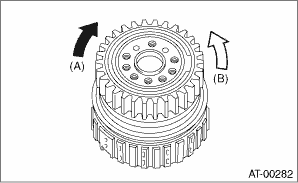
|
(A) |
Lock |
|
(B) |
Free |
1. Apply ATF to the new D-ring, then install to the 2-4 brake piston.
2. Install 2-4 brake piston to 2-4 brake piston retainer.
NOTE:
Be careful not to damage the D-ring.
|
(A) |
2-4 brake piston |
|
(B) |
2-4 brake piston retainer |
1. Install the needle bearing to inner race using ST and a press.
| ST 398497701 | INSTALLER |
2. Apply vaseline to the groove of the inner race and to the new seal ring.
3. Install two seal rings to the one-way clutch inner race.
|
(A) |
One-way clutch inner race |
|
(B) |
Seal ring |
1. Install the needle bearing, and then secure with the snap ring.
|
(A) |
Needle bearing |
|
(B) |
Snap ring |
2. Install the one-way clutch and one-way clutch inner race, then secure with the snap ring.
3. Set the inner race. Make sure that the clutch locks in the clockwise direction and rotates in the counterclockwise direction.
|
(A) |
Lock |
|
(B) |
Free |