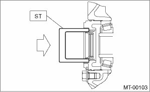
1. Replace the differential side retainer oil seal. 
| ST 18675AA000 | DIFFERENTIAL SIDE OIL SEAL INSTALLER |
NOTE:
Be sure to replace the differential side retainer oil seal after the removing the front drive shaft.
2. Install the transmission cushion rubber to the transmission assembly, and tighten bolt (A).
3. Install the transmission cushion rubber to the center crossmember, and tighten nut (B).
Tightening torque:
Bolt (A)
35 N·m (3.6 kgf-m, 25.8 ft-lb)
Nut (B)
35 N·m (3.6 kgf-m, 25.8 ft-lb)
4. Install the transmission onto the engine.
(1) Lift up the transmission gradually using a transmission jack.
(2) Engage at the spline section.
NOTE:
Be careful not to hit the main shaft against the clutch cover.
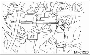
5. Loosen the turnbuckle of the ST while raising the transmission jack to return the engine to its original position.
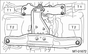
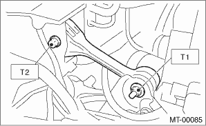
6. Install the front crossmember and rear crossmember.
Tightening torque:
T1: 70 N·m (7.1 kgf-m, 51.6 ft-lb)
T2: 140 N·m (14.3 kgf-m, 103.3 ft-lb)
7. Take out the transmission jack.
8. Tighten the bolts and nuts which hold the lower side of transmission to the engine.
Tightening torque:
50 N·m (5.1 kgf-m, 36.9 ft-lb)
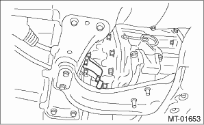
9. Connect the transmission to the engine.
(1) Install the starter.
(2) Tighten the bolts which hold the upper side of the transmission to the engine.
Tightening torque:
50 N·m (5.1 kgf-m, 36.9 ft-lb)
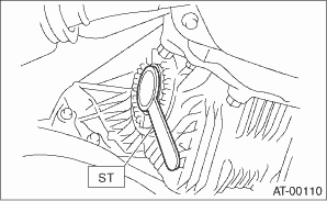
10. Remove the ST.
11. Install the pitching stopper.
Tightening torque:
T1: 50 N·m (5.1 kgf-m, 36.9 ft-lb)
T2: 58 N·m (5.9 kgf-m, 42.8 ft-lb)
12. Install the throttle body. (non-turbo model)
13. Lift up the vehicle.
14. Install the front drive shaft into the transmission.
| ST 28399SA010 | OIL SEAL PROTECTOR |
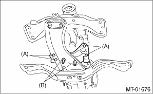
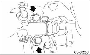
15. Insert the ball joints of the front arm into the housing, then tighten the installing bolts.
Tightening torque:
50 N·m (5.1 kgf-m, 36.9 ft-lb)
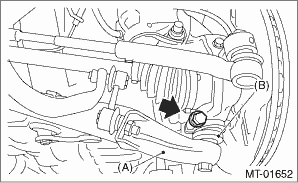
|
(A) |
Front arm |
|
(B) |
Ball joint |
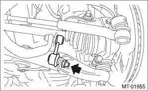
16. Attach the stabilizer link to the front arm.
Tightening torque:
30 N·m (3.1 kgf-m, 22.1 ft-lb)
17. Install the front vehicle height sensor.
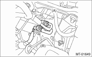
18. Attach the gear shift rod and stay.
(1) Attach the gear shift rod to the transmission.
Tightening torque:
12 N·m (1.2 kgf-m, 8.9 ft-lb)
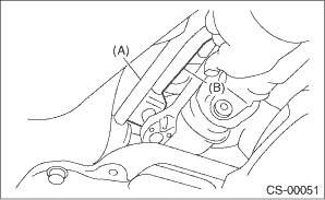
|
(A) |
Stay |
|
(B) |
Gear shift rod |
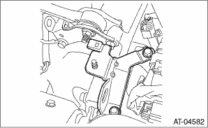
(2) Install the stay to the transmission bracket.
Tightening torque:
18 N·m (1.8 kgf-m, 13.3 ft-lb)
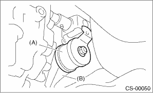
|
(A) |
Stay |
|
(B) |
Transmission bracket |
19. Install the propeller shaft.
20. Install the heat shield cover.
21. Install the hanger bracket to the transmission.
22. Install the rear exhaust pipe and muffler.
• Non-turbo model
• Turbo model
23. Install the front exhaust pipe. (non-turbo model)
24. Install the center exhaust pipe. (turbo model)
25. Install the universal joint. (turbo model)
26. Install the under cover.
27. Install the operating cylinder.
Tightening torque:
37 N·m (3.8 kgf-m, 27.3 ft-lb)
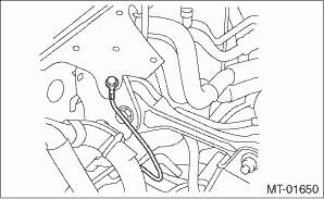
28. Install the ground cable.
Tightening torque:
13 N·m (1.3 kgf-m, 9.6 ft-lb)
29. Install the engine hanger rear, and then connect the engine harness connector. (non-turbo model)
Tightening torque:
16 N·m (1.6 kgf-m, 11.8 ft-lb)
|
(A) |
Engine harness connectors |
|
(B) |
Engine hanger rear |
30. Install the engine hanger. (turbo model)
Tightening torque:
16 N·m (1.6 kgf-m, 11.8 ft-lb)
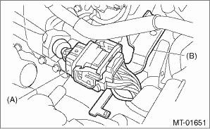
31. Connect the following connectors.
• Non-turbo model
|
(A) |
Neutral position switch connector (Brown) |
|
(B) |
Back-up light switch connector (Gray) |
|
(C) |
High-low switch connector (Black) |
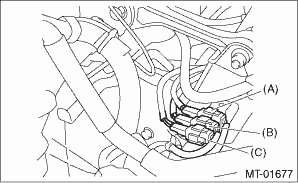
• Turbo model
|
(A) |
Neutral position and back-up light switch connector |
|
(B) |
Rear oxygen sensor connector |
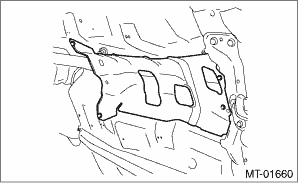
32. Install the air intake chamber stay. (non-turbo model)
Tightening torque:
16 N·m (1.6 kgf-m, 11.8 ft-lb)
33. Install the air intake chamber. (non-turbo model)
34. Install the intercooler. (turbo model)
35. Connect the ground cable to the battery.
36. Remove the lift arm from vehicle.
37. Re-initialize the auto head light beam leveler.