NOTE:
• Attach a cloth to the end of driven shaft (on the frictional side of the thrust needle bearing) to prevent damage during disassembly or reassembly.
• If necessary, use a new gear & hub assembly as a set, when replacing the gear or hub. Because these must engage at the specified point, avoid disassembly as much as possible. If it must be disassembled, mark the engaging point on the spline beforehand.
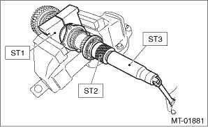
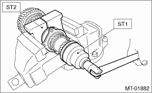
1. Flatten the tab of the lock nut. Remove the lock nut with ST1, ST2 and ST3.
| ST1 18680AA020 | HOLDER |
| ST2 18667AA020 | HOLDER |
| ST3 18662AA010 | SOCKET WRENCH (27) |
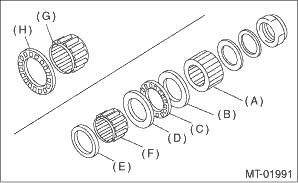
2. Draw out the drive pinion from driven shaft.
Remove the differential bevel gear sleeve, adjusting washer No. 1, adjusting washer No. 2, thrust bearing, needle bearing and drive pinion collar.
|
(A) |
Differential bevel gear sleeve |
|
(B) |
Adjusting washer No. 1 (25 × 36 × t) |
|
(C) |
Thrust bearing (25 × 36 × 2) |
|
(D) |
Adjusting washer No. 2 (25 × 36 × t) |
|
(E) |
Needle bearing (25 × 30 × 20) |
|
(F) |
Drive pinion collar |
|
(G) |
Needle bearing (30 × 37 × 23) |
|
(H) |
Thrust bearing (33 × 50 × 3) |
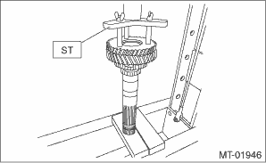
3. Remove the roller bearing and washer using ST and a press.
NOTE:
Do not reuse the roller bearing.
| ST 498077000 | REMOVER |
4. Flatten the tab of the lock nut. Remove the lock nut using ST1 and ST2.
| ST1 499987300 | SOCKET WRENCH (50) |
| ST2 18680AA020 | HOLDER |
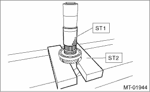
5. Remove the ball bearing, 6th driven gear and drive pinion spacer using the ST1, ST2 and a press.
| ST1 899754112 | PRESS |
| ST2 899714110 | REMOVER |
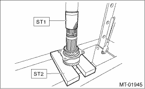
6. Remove the taper roller bearing and 3rd-4th driven gear using ST1, ST2 and a press.
| ST1 899754112 | PRESS |
| ST2 899714110 | REMOVER |
7. Remove the key.
8. Remove the 2nd driven gear, inner baulk ring, synchro cone, outer baulk ring and 1st-2nd coupling sleeve.
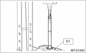
9. Remove the 1st driven gear, inner baulk ring, synchro cone, outer baulk ring, 2nd gear bushing and 1st-2nd synchronizer hub using ST and a press.
| ST 18762AA000 | COMPRESSOR SPECIAL TOOL |