• Hydraulic type
|
Trouble |
Possible cause |
Corrective action |
|
• Steering effort is heavy in all ranges. • Steering effort is heavy at stand still. • Steering wheel vibrates when turning. |
1. Pulley belt • Unequal length of pulley belts • Contact with oil or grease • Looseness or damage of the pulley belt • Poor uniformity of the pulley belt cross section • Pulley belt touches to pulley bottom • Poor revolution of pulleys (except oil pump pulley) • Poor revolution of oil pump pulley |
Adjust or replace. |
|
2. Tire and wheel • Improper tire out of specifications*1 • Improper wheel out of specifications*1 • Tires not properly inflated |
Replace or reinflate. | |
|
3. Fluid • Low fluid level • Air entry in fluid • Dust entry in fluid • Fluid deterioration • Inadequate warm up of fluid *2 |
Refill, bleed air, replace or instruct customer. | |
|
4. Idle speed • Lower idle speed • Excessive drop of idle speed at start or when turning the steering wheel *3 |
Adjust or instruct customer. | |
|
5. Measure the hydraulic pressure. |
Replace the problem parts. | |
|
6. Measure the steering wheel effort. |
Adjust or replace. | |
|
• Vehicle leads to one side or the other. • Returning force of steering wheel to center is poor. • Steering wheel vibrates when turning. |
1. Fluid line • Folded hose • Flattened pipe |
Correct or replace. |
|
2. Tire and wheel • Flat tire • Mixed use of different tires • Mixed use of different wheels • Abnormal wear of tire • Unequal tread remaining • Unequal pressure of tire |
Adjust, fix or replace. | |
|
3. Front alignment • Improper or unequal caster • Improper or unequal toe-in • Loose suspension connections |
Adjust or retighten. | |
|
4. Others • Damaged joint assembly • Unbalanced height • Unbalanced weight |
Replace, adjust or instruct customer. | |
|
5. Measure the steering wheel effort. |
Adjust or replace. |

*1 If the tires or wheels are wider than standard, the load to power steering system is increased. Accordingly, in a condition, for example before fluid warms-up, relief valve may work before reaching maximum turning angle. In this case, steering effort may be heavy. When the measured hydraulic pressure is normal, there is no abnormal thing.
*2 In cold weather, steering effort may be heavy due to increased flow resistance of cold fluid. After warming-up engine, turn the steering wheel from stop to stop several times to warm up fluid. If steering effort reduces normally, function is normal.
*3 In cold weather or with insufficient warm up of the engine, steering effort may be heavy due to excessive drop of idling when turning the steering wheel. In this case, start the vehicle with increasing engine speed than usual. If steering effort reduces normally, function is normal.
• Electric type
|
Trouble |
Possible cause |
Corrective action |
|
• Steering effort is heavy in all ranges. • Steering effort is heavy at stand still. • Steering wheel vibrates when turning. |
1. Tire and wheel • Improper tires out of specifications • Improper wheels out of specification • Tires not properly inflated |
Replace or reinflate. |
|
2. Measure the steering wheel effort. |
Adjust or replace. | |
|
• Vehicle leads to one side or the other. • Returning force of steering wheel to center is poor. • Steering wheel vibrates when turning. |
1. Tire and wheel • Flat tire • Mixed use of different tires • Mixed use of different wheels • Abnormal wear of tire • Unequal tread remaining • Unequal pressure of tire |
Adjust, fix or replace. |
|
2. Front wheel alignment • Improper or unequal caster • Improper or unequal toe-in • Loose suspension connections |
Adjust or retighten. | |
|
3. Measure the steering wheel effort. |
Adjust or replace. |
NOTE:
When performing repeated steering operation with the vehicle at standstill, the steering effort may be temporarily heavy because the heat generated in the system activates the power steering protection control. This is not a malfunction caused by the steering system. After a while, it will return to normal steering effort. (In this case, the steering warning light will not come on and there will be no DTC.)
1. NOISE & VIBRATION (HYDRAULIC TYPE)
CAUTION:
Do not keep the relief valve operated five seconds or more at any time or inner parts of the oil pump may be damaged due to rapid increase of fluid temperature.
NOTE:
• A screeching noise may be heard immediately after the engine start in extremely cold conditions. In this case, if the noise goes off during warm-up there is no abnormal function in the system. This is due to the fluid characteristics in extremely cold condition.
• The oil pump normally makes a small whining noise due to its mechanism. Even if a noise is heard when steering wheel is turned at stand still, there is no abnormal function in the system provided that the noise eliminates when the vehicle is driving.
• When turning the steering wheel with the brake applied when the vehicle is parked, a screeching noise may be generated by the brake disc and pads. This is not a fault in the steering system.
• There may be a small vibration around the steering devices when turning the steering wheel at standstill, even though the component parts are operating properly.
Hydraulic systems are likely to generate this kind of vibration as well as working noise and fluid noise because of combined conditions, i.e., road surface and tire surface, engine speed and turning speed of steering wheel, fluid temperature and braking condition.
These conditions do not indicate a problem in the system.
Confirm vibration for an AT model, by applying the parking brake on a concrete surface, shifting into the “D” range, and turning the steering wheel repeatedly from slow to rapid, step by step.
|
Trouble |
Possible cause |
Corrective action |
|
Hiss noise (continuous) While engine is running. |
Relief valve emits operating sound when steering wheel is completely turned in either direction. (Do not keep this condition 5 seconds or more.) |
Normal operation |
|
Relief valve emits operating sound when steering wheel is not turned. This means that the relief valve is defective. |
Replace the oil pump. | |
|
Rattling noise (intermittent) While engine is running. |
Interference with adjacent parts |
Check the clearance. Correct if necessary.
|
|
Loosened installation of oil pump, oil tank, pump bracket, gearbox or crossmember |
Retighten. | |
|
Loose oil pump pulley or other pulley(s) |
Retighten. | |
|
Looseness of linkage, play of steering, improper tightening (looseness) of suspension joint or steering column |
Retighten or replace. | |
|
Sound generates from the inside of gearbox or oil pump. |
Replace faulty parts in the gearbox or oil pump. | |
|
Knocking When turning steering wheel in both directions with small angle repeatedly at engine ON or OFF. |
Excessive backlash Loosened lock nut for adjusting backlash |
Adjust and retighten. |
|
Insufficient tightening or play in the tie-rod or tie-rod end |
Retighten or replace. | |
|
Grinding noise (continuous) While engine is running. |
Air in vane pump |
Inspect and retighten the fluid line connection. Refill the fluid and vent air. |
|
Vane pump seizing |
Replace the oil pump. | |
|
Oil pump pulley bearing seized |
Replace the oil pump. | |
|
Folded hose, flattened pipe |
Replace. | |
|
Squeal, squeak (intermittent or continuous) While engine is running. |
Improper adjustment of pulley belt Damaged or over tensioned pulley belt Unequal length of pulley belts |
Adjust or replace. (Replace two belts as a set.) |
|
Runout or dirty V-groove surface of oil pump pulley |
Clean or replace. | |
|
Sizzling noise (continuous) While engine is running. |
Fluid aeration |
Fix the faulty part causing aeration. Replace the fluid and vent air. |
|
Damaged pipe of gearbox |
Replace the pipe. | |
|
Faulty inside of hose or pipe Flattened hose or pipe |
Correct or replace. | |
|
Abnormal inside of oil tank |
Replace. | |
|
Removed oil tank cap |
Install cap. | |
|
Whistle (continuous) While engine is running. |
Faulty pipe of gearbox or faulty hose |
Replace the faulty parts of the gearbox or the hose. |
|
Whine or growl (intermittent or continuous) While engine is running with/without steering turned. |
Looseness of oil pump, oil pump bracket attachment |
Retighten. |
|
Fault inside of oil pump or hose |
Replace the oil pump or hose, if the noise can be heard when vehicle is running as well as being stopped. | |
|
Torque converter growl, air conditioner compression growl |
Remove the power steering pulley belt and check. | |
|
Grinding noise (continuous) While engine is running with the steering turned. |
Fault inside of gearbox |
Replace the faulty parts of gearbox. |
|
Faulty steering shaft bearing |
Apply grease or replace. | |
|
Occurs when turning the steering wheel with brakes (service or parking) applied. |
If the noise goes off when brake is released, it is normal. | |
|
Vibration While engine is running with/without steering turned. |
Engine speed is too low. |
Adjust, and notify customer. |
|
Air in vane pump |
Repair faulty part Vent air. | |
|
Damaged valve in oil pump or gearbox |
Replace the faulty parts in gearbox and oil pump. | |
|
Excessive play in steering, looseness of suspension parts |
Retighten. |
2. NOISE & VIBRATION (ELECTRIC TYPE)
NOTE:
• When turning the steering wheel with the brake applied when the vehicle is parked, a screeching noise may be generated by the brake disc and pads. This is not a fault in the steering system.
• There may be a small vibration around the steering devices when turning the steering wheel at standstill, even though the component parts are operating properly.
|
Trouble |
Possible cause |
Corrective action |
|
Rattling noise (intermittent) While engine is running. |
Interference with adjacent parts |
Check the clearance. Correct if necessary. |
|
Looseness of linkage, play of steering, improper tightening (looseness) of suspension joint or steering column |
Retighten or replace. | |
|
Noise emitted from inside of the gearbox |
Replace the gearbox assembly. | |
|
Knocking When turning steering wheel in both directions with small angle repeatedly at engine ON or OFF. |
Excessive backlash Loosened lock nut for adjusting backlash |
Adjust the backlash. When the noise remains after adjustment, replace the gearbox assembly. |
|
Insufficient tightening or play in the tie-rod or tie-rod end |
Retighten or replace. | |
|
Grinding noise (continuous) While engine is running. (While operating the steering) |
Fault inside of gearbox |
Replace the gearbox assembly. |
|
Faulty steering shaft bearing |
Apply grease or replace. | |
|
Occurs when turning the steering wheel with brakes (service or parking) applied. |
If the noise goes off when brake is released, it is normal. | |
|
Vibration While engine is running. (with/without steering operation.) |
Excessive play in steering, looseness of suspension parts |
Retighten. |
3. MEASUREMENT OF STEERING EFFORT (HYDRAULIC TYPE)
| STEP | CHECK | YES | NO |
|
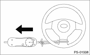
1) Stop the vehicle on paved road. 2) Start the engine. 3) Run the engine at idle. 4) Install a spring scale on the steering wheel. 5) Pull the spring scale at a right angle to the steering wheel, and measure both right and left steering wheel efforts.
NOTE: When turning the steering more quickly than necessary from a direction to the other direction at an engine speed of 2,000 rpm or more, steering effort may be heavy. This is caused by flow characteristic of the fluid in the oil pump and is not a defect. |
Is the steering effort less than 29.4 N (3.0 kgf, 6.6 lbf)? |
|
Adjust the backlash. |
|
Is the steering effort less than 294.2 N (30 kgf, 66.2 lbf)? |
|
Perform the adjustment. |
|
|
Is the steering effort less than 2.26 N (0.23 kgf, 0.51 lbf)? |
|
Check, adjust and replace if necessary. |
|
|
Is the difference of steering effort between right and left less than 20%? |
|
Check, adjust and replace if necessary. |
|
|
Is the swing torque of the universal joint less than 7.3 N (0.74 kgf, 1.64 lbf)? |
|
Replace with a new part. |
|
|
Is the swing torque of the universal joint less than 3.8 N (0.39 kgf, 0.86 lbf)? |
|
Replace with a new part. |
|
|
Does the front wheels have unsteady revolution or rattling, or does the brake drag? |
Inspect, readjust and replace if necessary. |
|
|
|
If the tie-rod ends of suspension have unsteady revolution or rattling? |
Inspect and replace if necessary. |
|
|
|
If the ball joints of suspension have unsteady revolution or rattling? |
Inspect and replace if necessary. |
|
|
|
Is the rotating resistance of steering gearbox 10.5 N (1.1 kgf, 2.4 lbf) for LHD model or less than 13 N (1.3 kgf, 2.9 lbf) for RHD model? Is the difference between right and left sides less than 20%? |
|
Readjust the backlash, and if ineffective, replace the faulty parts. |
|
|
Is the sliding resistance of steering gearbox 400 N (41 kgf, 90 lbf) for LHD model or less than 314 N (32 kgf, 71 lbf) for RHD model? Is the difference between the right and left sliding resistances less than 20%? |
Steering effort is normal. |
Readjust the backlash, and if ineffective, replace the faulty parts. |
4. MEASUREMENT OF STEERING EFFORT (ELECTRIC TYPE)
| STEP | CHECK | YES | NO |
|
Does the STEERING warning light illuminate? |
Read the DTC and perform inspection according to the diagnostics. |
|
|
|
1) Stop the vehicle on paved road. 2) Adjust the tire air pressure to the specified value. 3) Start the engine. 4) Run the engine at idle. 5) Install a spring scale on the steering wheel. 6) Pull the spring scale at a right angle to the steering wheel, and measure both right and left steering wheel efforts.
|
Is the steering effort less than 29.4 N (3.0 kgf, 6.6 lbf)? |
|
|
|
Is the steering effort less than 294.2 N (30 kgf, 66.2 lbf)? |
|
Perform the adjustment. |
|
|
Is the voltage 2.425 — 2.575 mV? |
|
Replace the gearbox assembly. |
|
|
Is the steering effort less than 2.26 N (0.23 kgf, 0.51 lbf)? |
|
Replace the steering column. |
|
|
Is the difference of steering effort between right and left less than 20%? |
|
Replace the steering column. |
|
|
Is the swing torque of the universal joint less than 7.3 N (0.74 kgf, 1.64 lbf)? |
|
Replace the universal joint with a new part. |
|
|
Is the swing torque of the universal joint less than 3.8 N (0.39 kgf, 0.86 lbf)? |
|
Replace the universal joint with a new part. |
|
|
Does the front wheels have unsteady revolution or rattling, or does the brake drag? |
Inspect, readjust and replace if necessary. |
|
|
|
If the tie-rod ends of suspension have unsteady revolution or rattling? |
Inspect and replace if necessary. |
|
|
|
If the ball joints of suspension have unsteady revolution or rattling? |
Inspect and replace if necessary. |
|
|
|
Is the rotating resistance of steering gearbox less than 13 N (1.3 kgf, 2.9 lbf)? Is the difference between right and left sides less than 20%? |
|
Replace the gearbox assembly. |
|
|
Is the sliding resistance of the steering gearbox less than 314 N (32 kgf, 71 lbf)? Is the difference between the right and left sliding resistances less than 20 %? |
Steering effort is normal. |
Replace the gearbox assembly. |
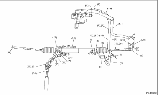
5. CLEARANCE CHECK (HYDRAULIC TYPE)
This table lists various clearances that must be correctly adjusted to ensure the normal vehicle driving without interfering noise, or any other faults.
• LHD model
|
Install locations |
Minimum allowance mm (in) |
|
(1) Crossmember to-Hose ASSY |
3 (0.12) |
|
(2) Front exhaust pipe to hose ASSY |
15 (0.59) |
|
(3) Front frame side to Hose ASSY |
10 (0.39) |
|
(4) Turbo cover to hose ASSY |
10 (0.39) |
|
(5) Master cylinder to return hose |
10 (0.39) |
|
(6) Master cylinder to hose clip |
10 (0.39) |
|
(7) VDC H/U to hose ASSY |
5 (0.20) |
|
(8) Air cleaner to hose ASSY |
5 (0.20) |
|
(9) Air boot to Hose ASSY |
10 (0.39) |
|
(10) Air cleaner hose to hose ASSY |
10 (0.39) |
|
(11) Blow-by hose to hose ASSY |
8 (0.31) |
|
(12) Over flow hose to hose ASSY |
8 (0.31) |
|
(13) Brake pipe to return hose |
10 (0.39) |
|
(14) Front suspension bracket to Return hose |
5 (0.20) |
|
(15) Front wheel apron to Return hose |
5 (0.20) |
|
(16) VDC H/U bracket to suction hose |
5 (0.20) |
|
(17) Air cleaner case to Suction hose |
5 (0.20) |
|
(18) Air intake duct to suction hose |
10 (0.39) |
|
(19) Air duct to suction hose |
10 (0.39) |
|
(20) Front wheel apron to Reservoir tank |
5 (0.20) |
|
(21) VDC H/U to reserve tank |
5 (0.20) |
|
(22) Valve housing to DOJ (5MT model) |
12 (0.47) |
|
(23) Valve housing to Crossmember (Hole) |
1 (0.04) |
|
(24) Cannon mount to crossmember |
There must be no contact |
|
(25) Pipe to crossmember |
5 (0.20) |
|
(26) Pipe to stabilizer |
15 (0.59) |
|
(27) Pipe to exhaust pipe |
18 (0.71) |
|
(28) Tie-rod end to brake dust cover |
2.5 (0.10) |
|
(29) Universal joint coupling to turbo cover |
15 (0.59) |
|
(30) Universal joint column side yoke to Master cylinder (Closest point of approach when the universal joint turns by 360°) |
5 (0.20) |
|
(31) Universal joint coupling to ATF level gauge |
10 (0.39) |
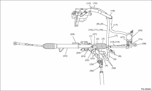
• RHD model
|
Install locations |
Minimum allowance mm (in) |
|
(1) Crossmember to-Hose ASSY |
3 (0.12) |
|
(2) Front exhaust pipe to hose ASSY |
15 (0.59) |
|
(3) Front frame side to Hose ASSY |
10 (0.39) |
|
(4) Turbo cover to hose ASSY |
10 (0.39) |
|
(5) Master cylinder to return hose |
10 (0.39) |
|
(6) Master cylinder to hose clip |
10 (0.39) |
|
(7) VDC H/U to hose ASSY |
5 (0.20) |
|
(8) Air cleaner to hose ASSY |
5 (0.20) |
|
(9) Air boot to Hose ASSY |
10 (0.39) |
|
(10) Air cleaner hose to hose ASSY |
10 (0.39) |
|
(11) Blow-by hose to hose ASSY |
8 (0.31) |
|
(12) Over flow hose to hose ASSY |
8 (0.31) |
|
(13) Brake pipe to return hose |
10 (0.39) |
|
(14) Front suspension bracket to Return hose |
5 (0.20) |
|
(15) Front wheel apron to Return hose |
5 (0.20) |
|
(16) VDC H/U bracket to suction hose |
5 (0.20) |
|
(17) Air cleaner case to Suction hose |
5 (0.20) |
|
(18) Air intake duct to suction hose |
10 (0.39) |
|
(19) Air duct to suction hose |
10 (0.39) |
|
(20) Front wheel apron to Reservoir tank |
5 (0.20) |
|
(21) VDC H/U to reserve tank |
5 (0.20) |
|
(22) Valve housing to DOJ (5MT model) |
12 (0.47) |
|
(23) Valve housing to Crossmember (Hole) |
1 (0.04) |
|
(24) Cannon mount to crossmember |
There must be no contact |
|
(25) Pipe to crossmember |
5 (0.20) |
|
(26) Pipe to stabilizer |
15 (0.59) |
|
(27) Pipe to exhaust pipe |
18 (0.71) |
|
(28) Tie-rod end to brake dust cover |
2.5 (0.10) |
|
(29) Universal joint coupling to turbo cover |
15 (0.59) |
|
(30) Universal joint column side yoke to Master cylinder (Closest point of approach when the universal joint turns by 360°) |
5 (0.20) |
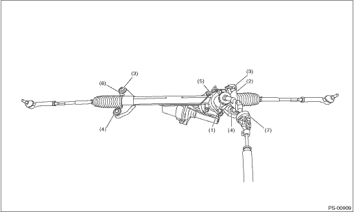
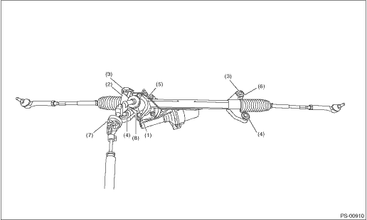
6. CLEARANCE CHECK (ELECTRIC TYPE)
This table lists various clearances that must be correctly adjusted to ensure the normal vehicle driving without interfering noise, or any other faults.
|
Install locations |
Minimum allowance mm (in) |
|
(1) Stub housing to DOJ (5MT model) |
15 (0.59) |
|
(2) Torque sensor to Crossmember |
5 (0.20) |
|
(3) Cannon mount to Crossmember |
There must be no contact |
|
(4) Cannon mount to Crossmember |
3 (0.12) |
|
(5) Stub housing to Engine mount |
15 (0.59) |
|
(6) Canon mount to Exhaust pipe |
15 (0.59) |
|
(7) Universal joint column side yoke to Master cylinder (Closest point of approach when the universal joint turns by 360°) |
5 (0.20) |
|
(8) Wheel housing to Exhaust pipe (LHD model) |
13 (0.51) |
• LHD model
• RHD model