1. Apply grease to the inside and outside of a new oil seal.
Steering grease:
VALIANT GREASE M2 (Part No. 003608001)
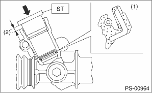
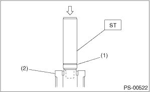
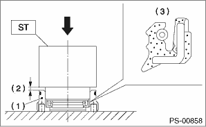
2. Check the direction and attachment location of the oil seal. Using the ST and a press, press-fit the oil seal into the gearbox.
CAUTION:
• Make sure to press fit the oil seal in all the way.
• The gap between the gearbox end face and the ST is to be approximately 1 mm (0.039 in) after press fitting.
| ST 34199AE130 | GEARBOX OIL SEAL INSTALLER |
|
(1) |
Oil seal |
|
(2) |
1 mm (0.039 in) |
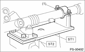
3. Attach the steering body to the ST as shown in the figure. Apply grease to the needle bearing.
| ST1 926200000 | STAND |
| ST2 34199AG000 | BOSS D |
CAUTION:
Make sure that there are no problems with the needle bearing. If faulty, replace with a new steering body.
|
(1) |
Clamp |
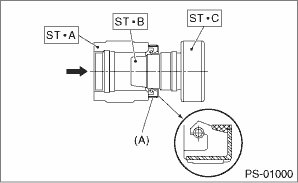
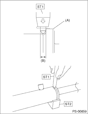
4. Using the ST A and ST B, attach the oil seal to ST C.
| ST 34199FE040 | INSTALLER A, B, C |
• INSTALLER A: 34199FE070
• INSTALLER B: 34199FE080
• INSTALLER C: 34199FE090
NOTE:
Face the oil seal in the direction as shown in the figure.
|
(A) |
Oil seal |
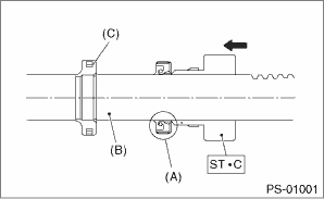
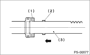
5. Insert the ST C with oil seal assembled from the gear side of rack. Remove the oil seal from ST C near piston, and then remove the ST C from rack.
|
(A) |
Oil seal |
|
(B) |
Rack |
|
(C) |
Piston |
6. Install the back-up washer from the gear side of rack.
|
(1) |
Oil seal |
|
(2) |
Back-up washer |
|
(3) |
Rack |
7. Apply a coat of grease to the grooves in rack, sliding surface of sleeve and sealing surface of piston. Then insert the rack into steering body from cylinder side.
8. Temporarily tighten a new holder to gearbox cylinder.
9. Mark a position 9 mm (0.35 in) from the end of the ST as indicated in the figure.
| ST 34199FE000 | INSTALLER & REMOVER |
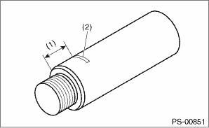
|
(1) |
9 mm (0.35 in) |
|
(2) |
Place a mark |
10. Set the ST to the end of rack.
| ST 34199FE000 | INSTALLER & REMOVER |
11. Using a press, press-fit until the mark placed on the ST is aligned to the end surface of the holder.
|
(1) |
Mark |
|
(2) |
Holder |
12. Remove the ST and holder.
13. Insert the outer side oil seal to the rack in the same procedure as step 4) to 5).
| ST 34199FE040 | INSTALLER A, B, C |
• INSTALLER A: 34199FE070
• INSTALLER B: 34199FE080
• INSTALLER C: 34199FE090
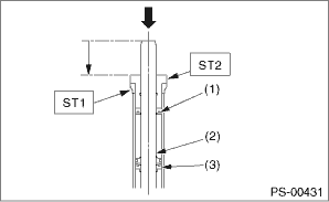
14. Place ST2 through the rack, and use the press to hold the rack and ST2.
Push in the rack until ST1 and ST2 contact each other, and the rack end face is aligned with the end face of ST2.
| ST1 34199FE050 | GUIDE |
| ST2 34199FE060 | INSTALLER |
|
(1) |
Outer side oil seal |
|
(2) |
Rack piston |
|
(3) |
Inner side oil seal |
15. Tighten the holder.
Tightening torque:
75 N·m (7.6 kgf-m, 55.3 ft-lb)
16. Using the ST, crimp one location less than 3 mm (0.12 in) from the holder.
CAUTION:
Be careful not to deform the holder.
| ST1 34099FA060 | PUNCH HOLDER |
| ST2 34199FE020 | BASE |
|
(A) |
Holder |
|
(B) |
3 mm (0.12 in) |
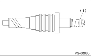
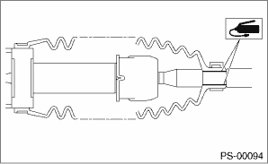
17. Roll a vinyl tape on the serration portion of valve assembly, and then apply grease on the tape surface.
|
(1) |
Vinyl tape |
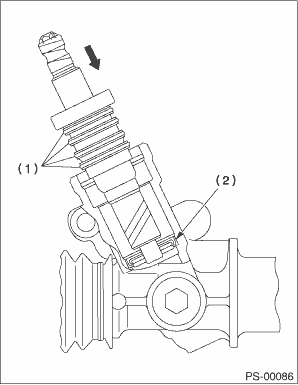
18. Apply grease to the gear teeth of the valve assembly, and while being careful not to damage the oil seals and seal rings, attach the valve assembly.
|
(1) |
Seal ring |
|
(2) |
Oil seal |
19. Replace the O-ring for the plug periphery with a new O-ring.
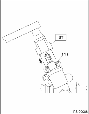
20. Apply grease on the oil seal circumference, and then press it into the plug using ST and a press.
| ST 34199AE110 | OIL SEAL PLUG INSTALLER |
CAUTION:
• Make sure to press fit the oil seal in all the way.
• The gap between the plug and the ST is to be approximately 1 mm (0.039 in) after press fitting.
|
(1) |
Plug |
|
(2) |
1 mm (0.039 in) |
|
(3) |
Oil seal |
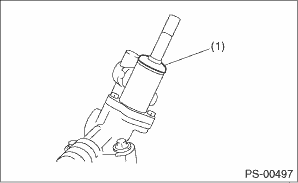
21. Using the ST, attach the plug.
| ST 34199AE090 | PLUG WRENCH |
Tightening torque:
64 N·m (6.5 kgf-m, 47.2 ft-lb)
|
(1) |
Plug |
22. Attach the dust cover, and remove the vinyl tape.
|
(1) |
Dust cover |
23. Temporarily tighten the tie-rod to the rack end, and then operate the rack from lock to lock for two or three times to make it fit in.
CAUTION:
Moving the rack for across its full stroke without installing tie-rods may damage the oil seal. Always install the left and right tie-rods.
24. Apply liquid gasket to 1/3 or more of entire perimeter of adjusting screw thread.
Liquid gasket:
THREE BOND 1141 (Part No. 004403006)
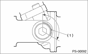
|
(1) |
Apply liquid gasket to 1/3 or more of the entire perimeter. |
25. Apply a coat of grease to the sliding surface of sleeve and seating surface of spring, and then insert the sleeve into steering body.
Charge the adjusting screw with grease, and then insert the spring into adjusting screw. Then install on the steering body.
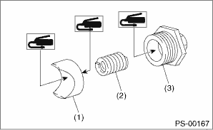
|
(1) |
Sleeve |
|
(2) |
Spring |
|
(3) |
Adjusting screw |
26. Tighten the adjusting screw to the specified torque, then loosen it.
Tightening torque:
9.8 N·m (1.0 kgf-m, 7.2 ft-lb)
27. Tighten the adjusting screw to the specified torque, then loosen it.
Tightening torque:
4.9 N·m (0.50 kgf-m, 3.6 ft-lb)
28. Tighten the adjusting screw to the specified torque, then loosen it by approximately 30°.
CAUTION:
Do not loosen by 37° or more.
Tightening torque:
4.9 N·m (0.50 kgf-m, 3.6 ft-lb)
29. Remove the tie-rod.
30. Check that play and looseness is within specifications. 
31. Install the lock nut. While holding the adjusting screw with wrench, tighten the lock nut using ST.
| ST 926230000 | SPANNER |
Tightening torque (lock nut):
39 N·m (4.0 kgf-m, 28.8 ft-lb)
NOTE:
Hold the adjusting screw with a wrench to prevent it from turning while tightening lock nut.
32. Attach the tie-rod to the rack.
Tightening torque:
90 N·m (9.2 kgf-m, 66.4 ft-lb)
NOTE:
Be careful that debris, dust, and other foreign objects do not become attached to the attachment surfaces of the rack and tie-rod.
33. Apply a coat of grease to the tie-rod groove, and then install the boot to the housing.
NOTE:
Make sure that the boot is installed without unusual inflation or deflation.
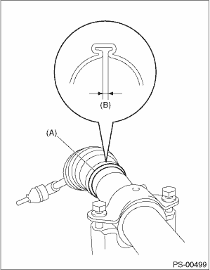
34. Using boot clamp pliers, crimp it so that the clearance of the boot band crimping section becomes 2 mm (0.08 in) or less.
NOTE:
Use a new boot band.
|
(A) |
Boot band |
|
(B) |
2 mm (0.08 in) or less |
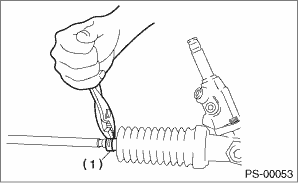
35. Fix the boot end with small clip.
|
(1) |
Clip |
36. After installing, check that the boot end is installed to the groove of the tie-rod.
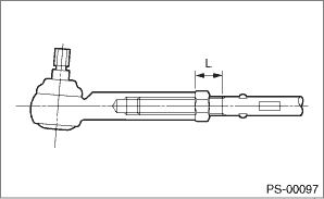
37. If the tie-rod end has been removed, screw in lock nut and tie-rod end to the screwed portion of tie-rod, and tighten the lock nut temporarily in a position as shown in the figure.
Installed tie-rod length L:
28 mm (1.1 in)
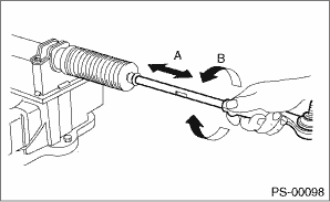
38. Inspect the gearbox as follows:
“A” Holding the tie-rod end, repeat lock to lock several times as quickly as possible.
“B” Holding the tie-rod end, turn it slowly at a radius several times as large as possible.
Finally, make sure that the boot is installed at the specified position without inflating.
39. Remove the gearbox from ST.
| ST1 926200000 | STAND |
| ST2 34199AG000 | BOSS D |
40. Attach pipe A and pipe B to the steering body and control valve housing.
Tightening torque:
T1: 20 N·m (2.0 kgf-m, 14.8 ft-lb)
T2: 24 N·m (2.4 kgf-m, 17.7 ft-lb)
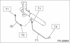
|
(1) |
Pipe A |
|
(2) |
Pipe B |