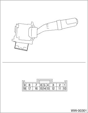
Inspect the continuity between each connector terminal.
• Except for KA model
| |
Switch position |
Terminal No. |
Standard |
|
Front |
OFF |
7 and 16 |
Less than 1 Ω |
|
INT |
7 and 16 |
Less than 1 Ω |
|
LO |
7 and 17 |
Less than 1 Ω |
|
HI |
8 and 17 |
Less than 1 Ω |
|
Washer ON |
2 and 11 |
Less than 1 Ω |
|
Rear |
OFF |
2 and 10
10 and 12
2 and 12 |
1 MΩ or more |
|
INT |
2 and 13 |
Less than 1 Ω |
|
ON |
2 and 10 |
Less than 1 Ω |
|
Washer ON |
2 and 12 |
Less than 1 Ω |
If continuity is not as specified, replace the switch.
• KA model
| |
Switch position |
Terminal No. |
Standard |
|
Front |
OFF |
3 and 12 |
Less than 1 Ω |
|
INT |
3 and 12 |
Less than 1 Ω |
|
LO |
3 and 11 |
Less than 1 Ω |
|
HI |
2 and 11 |
Less than 1 Ω |
|
Washer ON |
8 and 17 |
Less than 1 Ω |
|
Rear |
OFF |
8 and 16
16 and 18
8 and 18 |
1 MΩ or more |
|
ON |
8 and 18 |
Less than 1 Ω |
|
INT |
8 and 15 |
Less than 1 Ω |
|
Washer ON |
8 and 16 |
Less than 1 Ω |
If continuity is not as specified, replace the switch.
1. FRONT WIPER
1. Check with Subaru Select Monitor
When the front wiper switch is operated, check the input signal using the Subaru Select Monitor.
(1) Prepare the Subaru Select Monitor kit.
(2) Turn the ignition switch to ON.
(3) On «System Selection Menu» display, select {Integ. unit mode}.
(4) Select the {Current Data Display & Save}.
(5) Check the input signal when the front wiper switch is set to LO or HI.
Is the input signal normal?
• Yes → Finish the diagnosis.
• No →
1. Check the harness.
2. Check the ACC input voltage of the body integrated unit.
Connector & terminal
(B281) No. 5 (+) — Chassis ground (−):
3. Replace the body integrated unit. 
2. Check the intermittent operation (inspection of the wiper switch alone)
(1) Set voltmeter between the following terminals.
Connector & terminal
Except for KA model
(B70) No. 7 (+) — (B70) No. 2 (−):
KA model
(B70) No. 3 (+) — (B70) No. 8 (−):
(2) Connect the battery to the following terminals.
Connector & terminal
Except for KA model
(B70) No. 17 (+) — (B70) No. 2 & 16 (−):
KA model
(B70) No. 11 (+) — (B70) No. 8 & 12 (−):
(3) Turn the front wiper switch to INT.
(4) Connect the battery (+) to the following terminals for 5 seconds.
Connector & terminal
Except for KA model
(B70) No. 16:
(5) Connect the battery (−) to the following terminals and check the voltage between terminals during intermittent operation.
Connector & terminal
Except for KA model
Connect the battery (−) to the (B70) No. 16
Check the voltage between (B70) No. 7 (+) — (B70) No. 2 (−).
KA model
Connect the battery (−) to the (B70) No. 12
Check the voltage between (B70) No. 3 (+) — (B70) No. 8 (−).
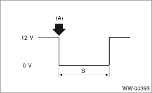
(6) Perform step (1) to (5) when intermittent control switch is in MIN or MAX, and replace the switch if the operation is not as specified.
Intermittent stationary time
|
(A): |
Connect the battery (−) to the terminal |
|
S: |
Intermittent downtime (sec.) |
2. REAR WIPER
1. Check with Subaru Select Monitor
1.CHECK INPUT OF REAR WIPER SWITCH.
Check the input from body integrated unit using the Subaru Select Monitor.
1) Prepare the Subaru Select Monitor kit.
2) Turn the ignition switch to ON.
3) On «System Selection Menu» display, select {Integ. unit mode}.
4) Select the {Current Data Display & Save}.
5) Check the input of the rear wiper switch.
|
|
|
|
2.CHECK HARNESS.
1) Disconnect the ground cable from battery.
2) Disconnect the connector of body integrated unit.
3) Disconnect the connector from wiper switch.
4) Measure the resistance between body integrated unit and wiper switch.
Connector & terminal
Except for KA model
(B281) No. 18 — (B70) No. 10:
(B281) No. 27 — (B70) No. 13:
(B281) No. 28 — (B70) No. 12:
KA model
(B281) No. 18 — (B70) No. 18:
(B281) No. 27 — (B70) No. 15:
(B281) No. 28 — (B70) No. 16:
|
Is the resistance less than 10 Ω?
|
|
Repair the harness between the body integrated unit and wiper switch.
|
3.CHECK INPUT VOLTAGE OF BODY INTEGRATED UNIT.
1) Connect the ground cable to battery.
2) Turn the ignition switch to ACC.
3) Check the input voltage of body integrated unit.
Connector & terminal
(B280) No. 7 (+) — Chassis ground (−):
|
Is the voltage 10 V or more?
|
|
Check the harness and fuse.
|
4.CHECK OUTPUT OF BODY INTEGRATED UNIT.
When the rear wiper switch is operated, check the output using the Subaru Select Monitor.
1) Turn the ignition switch to ON.
2) Operate the rear wiper switch and set to each position of ON and INT.
3) At this time, check the body integrated unit output.
|
When set to ON, is ON output continuous? When set to INT, is ON/OFF output repeated? (INT OFF time (when vehicle parked): 12 seconds)
|
Check the rear wiper motor circuit.
|
Replace the body integrated unit.
|
2. Check rear wiper motor circuit.
1.CHECK POWER SUPPLY CIRCUIT OF THE REAR WIPER MOTOR.
1) Disconnect the harness connector of the rear wiper motor.
2) Turn the ignition switch to ACC.
3) Measure the voltage between the rear wiper motor harness connector terminal and chassis ground.
Connector & terminal
(D43) No. 3 (+) — Chassis ground (−):
|
Is the voltage 10 V or more?
|
|
• Check the fuse (No. 23 in fuse & relay box).
• Check the fusible link (No. 7 in main fuse box).
|
2.CHECK GROUND CIRCUIT OF REAR WIPER MOTOR.
1) Turn the ignition switch to OFF.
2) Measure the resistance between the rear wiper motor harness connector terminal and chassis ground.
Connector & terminal
(D43) No. 3 — Chassis ground:
|
Is the resistance less than 10 Ω?
|
|
Repair the open circuit of the rear wiper motor ground circuit.
|
3.CHECK HARNESS BETWEEN BODY INTEGRATED UNIT AND REAR WIPER MOTOR.
1) Turn the ignition switch to OFF.
2) Disconnect the harness connector of body integrated unit.
3) Disconnect the harness connector of the rear wiper motor.
4) Measure the resistance between the harness connector terminals of the body integrated unit and rear wiper motor.
Connector & terminal
(B279) No. 8 — (D43) No. 1:
(B279) No. 9 — (D43) No. 2:
|
Is the resistance less than 10 Ω?
|
|
Repair the open circuit of the harness between body integrated unit and rear wiper motor.
|
4.CHECK INPUT VOLTAGE OF BODY INTEGRATED UNIT.
1) Turn the ignition switch to ACC.
2) Check the input voltage of body integrated unit.
Connector & terminal
(B279) No. 21 (+) — Chassis ground (−):
|
Is the voltage 10 V or more?
|
|
Check the harness and fuse.
|
5.CHECK OUTPUT OF BODY INTEGRATED UNIT.
1) Connect the harness connector of body integrated unit.
2) Disconnect the connector of the rear wiper motor.
3) Turn the ignition switch to ACC.
4) Measure the voltage between rear wiper motor connector and chassis ground.
Connector & terminal
(B279) No. 9 (+) — Chassis ground (−):
|
Is the voltage less than 1.5 V when rear wiper switch is OFF, and is the voltage 10 V or more when rear wiper switch is ON?
|
|
Replace the body integrated unit.
|
6.CHECK OPERATION OF REAR WIPER MOTOR.
1) Remove the rear wiper motor.
2) Check the rear wiper motor.
|
Does the rear wiper motor rotate normally?
|
|
Replace the rear wiper motor.
|