1. Check for scratches, swelling, corrosion, traces of fluid leakage on the brake hoses or pipe joints.
2. Check the possibility of adjacent parts interfering with brake pipes/hoses during driving, and loose connections/clamps.
3. Check any trace of fluid leakage, scratches, etc. on master cylinder, wheel cylinder and pressure control valve.
NOTE:
• When the brake fluid level in the reservoir tank is lower than specified limit, the brake warning light on the combination meter will come on.
• Visually check the brake hose for damage. (Use a mirror where it is difficult to see)
|
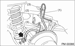
(1) |
Front brake hose |
|
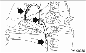
(2) |
Front brake pipe |
|
(1) |
Rear brake pipe |
|
(2) |
Rear brake hose |
|
(3) |
Clamp |
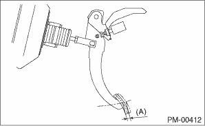
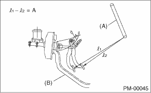
1. Check the free play of brake pedal with a force of less than 10 N (1 kgf, 2 lbf).
Brake pedal free play:
0.5 — 2.0 mm (0.02 — 0.08 in)
|
(A) |
Pedal free play |
2. If the free play is out of specifications above, adjust the brake pedal as follows.
(1) Make sure the engine is off. (No vacuum is applied to brake booster.)
(2) Inspect that there is play between brake booster clevis and pin at brake pedal installing portion.
[Depress brake pedal pad with a force of 10 N (1 kgf, 2 lbf) or less to a stroke of 0.5 to 2.0 mm (0.02 to 0.08 in).]?
(3) Pull the brake pedal by hand.
(4) If there is no play between the clevis pin and the clevis, rotate the brake switch to the left.
(5) Loosen the operating rod locknut, rotate the operating rod, adjust the pedal to the specified height and tighten the locknut.
Locknut tightening torque:
22 N·m (2.2 kgf-m, 16.2 ft-lb)
Pedal height L:
LHD model
150 — 160 mm (5.91 — 6.30 in)
RHD model
162 — 172 mm (6.38 — 6.77 in)
Brake pedal free play:
0.5 — 2.0 mm (0.02 — 0.08 in)
|
(A) |
Pedal free play |
(6) While pulling up the brake pedal, insert the brake switch until the end of the brake switch screw contacts the stopper.
(7) With the end of the brake switch screw pushed against the stopper, turn the switch to the right and secure the switch.
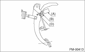
(8) Check that gap C between the stopper and the end of the brake switch screw is within the specification.
|
(A) |
Brake switch |
|
(B) |
Switch clip |
|
(C) |
1.35±0.61 mm (0.05±0.02 in) |
|
(D) |
Stopper |
(9) Pull up the pedal pad and check the play. Check that the stop light goes out when the pedal is not pressed.
3. Check the pedal stroke.
While the engine is idling, depress the brake pedal with a 490 N (50 kgf, 110 lbf) load and measure the distance between the brake pedal and steering wheel. With the brake pedal released, measure the distance between pedal and steering wheel again. The difference between the two measured values must be the specified value or less. If the measured value is specification or more, there is possibility of entering air in hydraulic unit.
Brake pedal stroke A:
Gasoline engine model: 95 mm (3.7 in)/ 490 N (50 kgf, 110 lbf) or less
Diesel engine model: 115 mm (4.5 in)/ 490 N (50 kgf, 110 lbf) or less
|
(A) |
Steering wheel |
|
(B) |
Toe board |
4. Check to see if air is in the hydraulic brake line by the feel of pedal operation. If air appears to exist in the line, bleed it from the system.
5. Check for even operation of all brakes, using a brake tester or by driving the vehicle for a short distance on a straight road.
1. With the engine off, depress the brake pedal several times applying the same pedal force. Make sure the travel distance should not change.
2. With the brake pedal depressed, start the engine. Check that the pedal moves slightly toward the floor.
3. With the brake pedal depressed, stop the engine and keep the pedal depressed for 30 seconds. Check that the pedal height does not change.
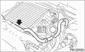
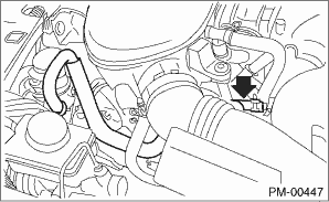
4. A check valve is built into the vacuum hose. Disconnect the vacuum hose to inspect function of the check valve.
Blow air into vacuum hose from the end of the brake booster side. Check that the air flows out to the engine side of the air hose. Next blow air into hose from engine side. Check that the air does not flow out to the brake booster side.
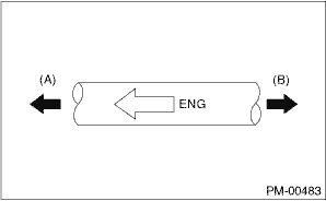
Replace the both check valve and vacuum hose if the check valve is faulty. Engine side of vacuum hose is indicated by marking “ENG” as shown.
|
(A) |
Engine side |
|
(B) |
Brake booster side |
5. Check the vacuum hose for cracks or other damage.
CAUTION:
When installing the vacuum hose on the engine and brake booster, do not use soapy water or lubricating oil on their connections.
6. Check that the vacuum hose is securely mounted.